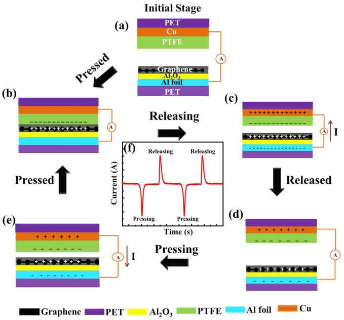
Figure 5.
Schematic diagram showing the working mechanism of Gr-TENG with Al2O3. (a) Initial stage of two different triboelectric layers when no external impact is applied. (b) Triboelectric charges are generated on the surfaces of graphene and PTFE when they are in contact with each other. (c) Separation of graphene and the PTFE triboelectric layer begins. The current flows from the bottom electrode (graphene) to the top electrode (PTFE) to maintain electrical equilibrium. (d) Complete separation of the graphene and PTFE triboelectric layer and reaching electrical equilibrium causes no electron flow. (e) Pressing the graphene and PTFE triboelectric layer into contact again causes the current to flow from the top electrode to the bottom electrode. (f) One typical signal of Gr-TENG with Al2O3 upon pressing and releasing.

