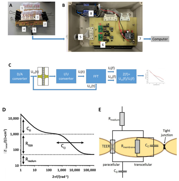
Figure 3.
TEER measurement setup: (A) Chip (1) with medium-filled reservoirs (3) mounted on electrical interface fixture (2). LEDs (4) indicate proper connection of chip contacts to the measurement system. A cable (5) delivers the voltage signal, Uin(t), to the 10 culture areas simultaneously and feeds individual current signals, UI(t), to the current-to-voltage converter (6) in the measurement system. (B) Measurement system comprising a power supply (8), a digital/analog converter (D/A), current-to-voltage converters (I/U), digital switches, and data acquisition board (National Instruments USB9012) connected to a computer via USB-cable (7). (C) Schematic circuit diagram: the D/A-converter provides a voltage signal synthesized from a set of discrete frequencies to the chip. Voltage amplitudes may be adjusted by the LabView application software. Fourier transform of both current and voltage signals yields frequency spectra thereof and allows for calculation of the impedance spectra Z(f) of 10 channels within seconds. (D) Impedance spectra measured in the MFC exhibit distinct features reflecting the electrical properties (adapted from [46] with permission) (E) of electrodes, CEl, medium, Rmedium, and interface with or without cellular barrier, TEER, Rmembrane and Cdl.

