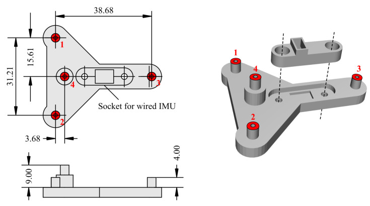
Figure A2.
Dimensions (in mm) of the headborne 3D-printed support used for concurrent IMU and optical motion capture measurements (see also Figure 2a). The wired IMU was secured in a dedicated socket using an additional piece (right) and a pair of nylon screws and nuts. Red areas represent the location of infrared reflective markers. Numbers assigned to the markers are indicated in red.

