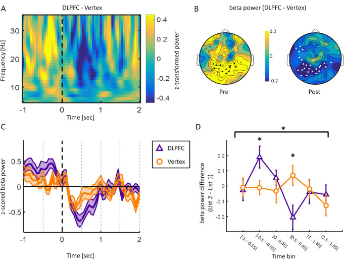
Fig 3. EEG results (only later remembered trials analysed).
(A) Time frequency plot for the difference between DLPFC and vertex during List 2 encoding averaged over electrode cluster demonstrating a significant negative difference (i.e., less power for DLPFC compared to vertex) between the DLPFC and vertex group in the beta frequency range poststimulus. Dashed line indicates word onset. (B) Topographies depicting beta power (13 to 30 Hz) difference between DLPFC and vertex stimulation in time windows of interest (pre: −0.5 s to −0.05 s; post = 0 to 1 s). White circles depict significant negative electrode cluster poststimulus. Black circles show electrodes within the negative cluster showing a positive difference prestimulus. (C) Time course of beta power (13 to 30 Hz) averaged over the negative electrode cluster shown in B. Shaded area represents standard error of the mean. Black dashed line indicates word onset. Grey dashed lines depict time bins. (D) Beta power difference (List 2 − List 1) over significant negative electrode cluster split by rTMS. Error bars show standard error of the mean. Data were split into 6 nonoverlapping time bins: [−1 s to −0.55 s]; [−0.5 s to −0.05 s]; [0 s to 0.45 s]; [0.5 s to 0.95 s]; [1 s to 1.45 s]; [1.5 s to 1.95 s]. The data and scripts used to generate this figure can be found at https://osf.io/dyxjv/. DLPFC, dorsolateral prefrontal cortex; EEG, electroencephalography; rTMS, repetitive transcranial magnetic stimulation.

