

Abstract
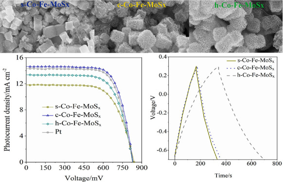
In the present study, three types of specific solid, core–shell, and hollow structured cobalt and iron co-doped MoS2 nanocubes (denoted as s-Co-Fe-MoSx, c-Co-Fe-MoSx, and h-Co-Fe-MoSx) are controllably synthesized for the first time by regulating the reactant mass ratios. The prepared Co-Fe-MoSx nanocubes can function as a counter electrode in dye-sensitized and perovskite solar cells (DSCs and PSCs) and a working electrode in a supercapacitor. In the DSC system, the c-Co-Fe-MoSx nanocubes exhibit the maximum catalytic activity to the Co3+/2+ redox couple regeneration, and the device achieves a power conversion efficiency (PCE) of 8.69%, significantly higher than the devices using s-Co-Fe-MoSx (6.61%) and h-Co-Fe-MoSx (7.63%) counter electrodes. Similarly, all of the prepared Co-Fe-MoSx nanocubes show decent activity in PSCs and the device using the c-Co-Fe-MoSx counter electrode achieves the highest PCE of 6.88%. It is worth noting that, as the supercapacitor working electrode, the h-Co-Fe-MoSx exhibits a specific capacitance of 85.4 F g–1, significantly higher than the parallel values achieved by the s-Co-Fe-MoSx and c-Co-Fe-MoSx electrodes under identical conditions.
1. Introduction
Developing clean energy and exploring highly effective energy conversion and storage materials and devices are critical for energy crisis and emission reduction as well as sustainable development.1−4 Among various energy conversion and storage devices, dye-sensitized solar cells (DSCs), a typical third-generation photovoltaic device, exhibit the merits of a simple assembly procedure, easy integration into the photoelectric building, and a high-power conversion efficiency (PCE) under weak illumination. Thus, DSCs turn out to be a promising indoor power source.5,6 To exploit the electric energy generated by the DSCs conveniently and efficiently, an auxiliary energy storage device should be employed. A supercapacitor refers to a potential energy storage device exhibiting advantages of a high-power density, a fast charge–discharge rate, and excellent stability.7,8 As early as 2005, the Miyasaka group attempted to fabricate a typical device integrating power conversion and storage, in which DSCs act as the energy conversion component, and the supercapacitor serves as the energy storage component.9 In other words, the integrated device can be recognized as a photocapacitor combining the photoelectric conversion capability exhibited by DSCs and the energy storage capability exhibited by a supercapacitor. On the whole, the integrated photocapacitor comprises three electrodes; a vital shared electrode acts as the counter electrode in the DSCs, and it also serves as the working electrode in the supercapacitor.10 Obviously, the energy conversion component can be replaced by other photovoltaic devices, such as the perovskite solar cells (PSCs). The photoelectric conversion and energy storage efficiency exhibited by the photocapacitor are closely related to the shared electrode materials, so the development of highly effective multifunctional electrode materials has constantly been the research hotspot for the DSCs, PSCs, and supercapacitor.11
Specific to the DSCs, the counter electrode acts as a catalyst for the redox couple regeneration, and Pt is the common counter electrode material. Though Pt exhibits a high activity as the counter electrode, the high cost and limited reserves are the serious obstacles in its commercial applications. Furthermore, Pt can be corroded by the electrolyte that impacts the PCE and stability of the device simultaneously.12 Moreover, Pt cannot act as a working electrode in the supercapacitor. Accordingly, the exploration of low-cost, high-efficiency, and stable counter electrode materials exhibiting a capacitive ability can down-regulate the fabrication cost, enhance the PCE and stability of DSCs, and satisfy the requirements of the supercapacitor. Besides Pt, carbon materials,13 transition metal compounds,14−19 conductive polymers,20 and alloys21−23 have been introduced into the DSCs as the counter electrode. Among the transition metal compounds, transition metal sulfides were widely employed in the DSCs as the counter electrode, such as CoS, MoS2, WS2, PbS, Ag2S, CuS, etc.24−27 The same as DSCs, exploring a low-cost and stable counter electrode to replace the common Au and Ag in PSCs is also a challenging work. The generally used metal-free counter electrodes are carbon materials, and no report can be found about the metal sulfide counter electrode in PSCs.
For the supercapacitor, the extensively used electrode materials include carbon,28−30 oxides,31,32 and polymers.8,33 In addition, transition metal sulfides have been introduced as the supercapacitor electrodes over the past few years. For instance, transition metal sulfides and molybdenum sulfides (MoSx, x = 2 or 3) have been intensively investigated as the electrode materials in energy conversion and storage.34 However, the commercial application of MoSx materials remains restricted by their intrinsic defects (e.g., insufficient electrochemical active sites, a pronounced volume variation, and a relatively low electrical conductivity for energy conversion and storage devices).35 To tackle down the mentioned problems, a feasible path is to design specific nanostructured hollow multiple metal sulfide with a large surface area and unique structural features that can show great advantages for electrochemical proprieties.36,37 Moreover, heteroatom doping refers to another feasible path to improve the electrode activity of MoSx.38,39 For instance, Wang et al. exploited transition metal atom (Fe, Co, Ni, and Cu)-doped MoS2 nanofilms. They proved that the exchange current density of MoS2 could be improved by incorporating transition metal atoms in the hydrogen evolution reaction system.38
As indicated from the mentioned research, MoSx is expected to be an efficient electrode in the DSCs and the supercapacitor devices. In addition, designing ternary or multiple sulfide compounds and constructing hollow architecture and electronic structure modulation by the dopants of transition metal have been proven as effective methods for enhancing the performance of the sulfide electrodes in both energy conversion and storage fields. In this study, a novel metal–organic framework (MOF)-engaged strategy was adopted to synthesize cobalt and iron-doped MoS2 nanocubes via the reaction between cobalt iron Prussian blue analogue (Co-Fe PBA) nanocubes and ammonium thiomolybdate through the solvothermal method. A specific structural evolution process from solid, core–shell, and hollow nanocubes was observed by altering the reactant mass ratios. Furthermore, the prepared solid, core–shell, and hollow structured Co-Fe-MoSx was introduced in DSCs as the counter electrode and in the supercapacitor as the working electrode to assess the activity of the three types of Co-Fe-MoSx. Finally, the Co-Fe-MoSx samples were also introduced into PSCs as counter electrode materials for the first time.
2. Results and Discussion
2.1. Materials Physical Analysis
Figure 1 presents the X-ray diffraction (XRD) patterns of the three types of Co-Fe-MoSx samples. The weak peaks at 14.0, 32.9, and 58.7° indicated the (002), (100) and (110) crystal planes of hexagonal MoS2 (PDF no. 37-1492), respectively. Obviously, the MoS2 phase exhibited a weak crystallinity, which cannot be improved by regulating the mass ratios of Co-Fe PBA to (NH4)2MoS4. The specific diffraction peaks located at 26.7, 32.8, and 55.1° belong to the (220, 222, 440) crystal planes of cubic Co3S4 (PDF no. 47-1738), respectively. Furthermore, the peaks at 30.4 and 52.3° refer to the (004, 213) crystal planes of hexagonal FeS (PDF no. 37-0477), respectively. Thus, the prepared Co-Fe-MoSx samples could be considered a multiple sulfide compound containing MoS2, Co3S4, and FeS. Moreover, a small amount of impurity of elemental sulfur (S) can be observed evidenced by the peak at around 20.2°. As proven from the XRD results, Co-Fe PBA nanocubes were converted into Co-Fe-MoSx after the hydrothermal reaction with (NH4)2MoS4 at a mass ratio of 1:1.
Figure 1.

XRD patterns of the prepared Co-Fe-MoSx products (s-Co-Fe-MoSx, c-Co-Fe-MoSx, and h-Co-Fe-MoSx).
To characterize the morphologies of the prepared Co-Fe-MoSx, scanning electron microscopy (SEM) and transmission electron microscopy (TEM) characterizations were performed. As illustrated in Figure S1, the Co-Fe PBA precursor exhibited a regular cube shape with an average side length of 200 nm. Smooth edges and slight embossments could be observed in the respective surface of the Co-Fe PBA nanocubes. According to the SEM and TEM images in Figure 2a and Figure 2b, respectively, Co-Fe-MoSx maintained the cube shape, while the solid construction was converted to a core–shell structure. In the core–shell Co-Fe-MoSx structured nanocubes (c-Co-Fe-MoSx), the side length of the shell was around 300 nm, while the side length of the core was around 200 nm. Both the SEM and TEM images proved that the shell was constructed by amounts of ultrathin curly MoS2 nanosheets, complying with a previous report.40 Moreover, as revealed from the elemental mapping images (Figure 2c–h), all the key elements of Fe, Co, Mo, and S were distributed uniformly throughout the core–shell Co-Fe-MoSx nanocubes. Energy-dispersive X-ray spectroscopy (EDS) (Figure 2i) showed that, compared with Fe and Co elements, Mo and S elements exhibited significantly higher signal intensities, demonstrating that MoS2 could be the dominant component in c-Co-Fe-MoSx, and the molar ratios of Fe and Co were 5.53 and 8.36%, respectively.
Figure 2.

SEM (a) and TEM (b) images of c-Co-Fe-MoSx synthesized with mass ratios of (NH4)2MoS4 to Co-Fe-PBA of 1:1; elemental mapping images of (c) c-Co-Fe-MoSx, (d) O, (e) Mo, (f) S, (g) Fe, and (h) Co; (i) EDS spectrum of the c-Co-Fe-MoSx.
The SEM and TEM images in Figure 3 compare the surface morphologies and internal structure of the synthesized Co-Fe-MoSx samples with the mass ratios of (NH4)2MoS4 to Co-Fe PBA of 1:2, 1:1, and 2:1. When the mass ratios of (NH4)2MoS4 to Co-Fe PBA were controlled at 1:2, a solid structured Co-Fe-MoSx nanocube was achieved, which was expressed as s-Co-Fe-MoSx, and the side length of the cubes was around 200–300 nm. A small number of ultrathin curly MoS2 nanosheets were scattered on the solid cube surface. As the mass ratio increased to 1:1, a specific core–shell Co-Fe-MoSx nanocube was obtained (Figure 3c,d), which was denoted as c-Co-Fe-MoSx whose physical properties were analyzed above. When the mass ratio of (NH4)2MoS4 further increased to 2:1, the solid Co-Fe PBA nanocubes were thoroughly converted into hollow structured Co-Fe-MoSx nanocubes (h-Co-Fe-MoSx) with the well-defined cubic voids in the nanocubes. The side length of the hollow cubes was around 300 nm. As compared with s-Co-Fe-MoSx, c-Co-Fe-MoSx and h-Co-Fe-MoSx showed significantly rough surfaces with bushy embedded curly nanosheets. It is worth noting that the rough surface and inserted nanosheets could expand the specific surface area and increase the catalytic active sites.41 As confirmed from the EDS spectra in Figure S2, the key elements of Fe, Co, Mo, and S were observed in all three Co-Fe-MoSx nanocube samples without any obvious fluctuation for the signal intensities of these elements.
Figure 3.

SEM (a) and TEM (b) images of s-Co-Fe-MoSx; SEM (c) and TEM (d) images of c-Co-Fe-MoSx; SEM (e) and TEM (f) images of h-Co-Fe-MoSx.
X-ray photoelectron spectroscopy (XPS) was further conducted to verify the surface chemical states of the elements in all the three Co-Fe-MoSx nanocube samples. The panoramic view of the XPS spectra in Figure S3 demonstrates the appearance of Co, Fe, Mo, S, N, O, and C (as the reference) elements in all prepared s-Co-Fe-MoSx, c-Co-Fe-MoSx, and h-Co-Fe-MoSx nanocubes. As shown in Figure 4, a fine analysis of the key elements in c-Co-Fe-MoSx was conducted. Figure 4a presents two peaks located at 235.5 and 232.4 eV, belonging to Mo 3d3/2 and Mo 3d5/2 of the tetravalent Mo4+ cation, respectively. Moreover, the peak at 228.9 eV belongs to S 2s. In Figure 4b, the two peaks located at 163.1 and 161.9 eV refer to S 2p1/2 and S 2p3/2, respectively, thereby conforming with the existence of the divalent S2– anion. Accordingly, the XPS analysis of Mo and S elements directly evidenced the MoS2 phase in Co-Fe-MoSx. Figure 4c presents the Co 2p region comprising two spin–orbit doublets, and the peaks at 803.0 and 786.4 eV belong to Co 2p1/2 and Co 2p3/2 of the divalent Co2+ cation, respectively. Likewise, the peaks located at 797.2 and 781.6 eV belong to Co 2p1/2 and Co 2p3/2 of the trivalent Co3+ cation, respectively, which demonstrated that the typical Co3S4 phase is in the Co-Fe-MoSx sample. According to Figure 4d, the peaks at 724.2 and 711.3 eV belong to Fe 2p1/2 and Fe 2p3/2 of the divalent Fe2+ cations, respectively, which could be coordinated with the S2– anion to form FeS. A trace of Fe2+ cations was oxidized to Fe3+ evidenced by the peaks located at 726.4 and 714.6 eV that, respectively, belong to Fe 2p1/2 and Fe 2p3/2 for Fe3+. Interestingly, a slight difference could be identified among the XPS spectra of the three Co-Fe-MoSx nanocubes. A shake-up satellite peak denoted as “Sat.” is presented for Fe 2p in c-Co-Fe-MoSx (Figure 4d), while no obvious Sat. peak for Co 2p (Figure 4c) can be found. However, according to the XPS spectra of the prepared Co-Fe-MoSx nanocubes in Figures S3–S5, a Sat. peak can be observed for Co 2p in h-Co-Fe-MoSx.
Figure 4.

XPS spectra of h-Co-Fe-MoSx; (a) Mo 3d and S 2s; (b) S 2p; (c) Co 2p; (d) Fe 2p.
The specific surface area and porosity properties of the three Co-Fe-MoSx nanocube samples were assessed by the N2 adsorption–desorption measurements. Figures S6–S8 plot the nitrogen adsorption–desorption curves of the three Co-Fe-MoSx samples, which overall exhibited the indistinct hysteresis loops in the range of 0.45–1.0 P/P0, so the existence of mesoporous structures was demonstrated. The Brunauer–Emmett–Teller (BET) surface areas of s-Co-Fe-MoSx, c-Co-Fe-MoSx, and h-Co-Fe-MoSx were 10.5, 12.8, and 13.7 m2 g–1, respectively. The specific surface area was obviously expanded as the augment of the MoS42– in the reaction systems, well complying with the morphology analysis. Furthermore, the pore size distributions of the Co-Fe-MoSx samples were calculated by using the Barrett–Joyner–Halenda (BJH) method. As shown in the inset, there are broad peaks ranging from 20 to 80 nm for the three types of Co-Fe-MoSx nanocubes, thereby demonstrating the existence of considerable mesopores and macropores in the nanocubes.
2.2. Electrochemical Analysis of the Prepared Co-Fe-MoSx Nanocubes in DSCs and PSCs
In the DSC system, the counter electrode could act as a catalyst for the regeneration of the redox couple in the electrolyte. Cyclic voltammetry (CV) measurements could be the effective tools to assess the catalytic activities of the counter electrode. Figure 5a presents typical cyclic voltammograms for s-Co-Fe-MoSx, c-Co-Fe-MoSx, h-Co-Fe-MoSx, and Pt electrodes in the Co3+/2+ electrolyte. All the Co-Fe-MoSx electrodes present a pair of redox peaks belonging to the redox reaction between Co3+ and Co2+. For s-Co-Fe-MoSx, c-Co-Fe-MoSx, and h-Co-Fe-MoSx, the cathodic peaks are located at 0.097, 0.126, and 0.115 V, while the anodic peaks are identified at 0.318, 0.267, and 0.288 V, respectively. Obviously, the cathodic peaks of the c-Co-Fe-MoSx and h-Co-Fe-MoSx shifted to the positive potential, while the anodic peaks shifted to the negative potential as compared with the s-Co-Fe-MoSx counterparts. Thus, c-Co-Fe-MoSx and h-Co-Fe-MoSx achieved the peak-to-peak separation (ΔEP) values of 0.141 (c-Co-Fe-MoSx) and 0.173 V (h-Co-Fe-MoSx), significantly lower than the counterpart of s-Co-Fe-MoSx (0.221 V). As a benchmark, Pt achieved the cathodic and anodic peaks at 0.122 and 0.281 V, and the ΔEP was 0.159 V. Theoretically, the charge transfer rate (ks) varies inversely with ΔEP values. Thus, the ks value for the c-Co-Fe-MoSx can be considered the highest among the three Co-Fe-MoSx samples, thereby indicating the optimal electrode reversibility.42,43 On the counter electrode surface, the regenerated speed of the Co3+/2+ redox couple was related to the cathodic peak current densities.44 Obviously, c-Co-Fe-MoSx exhibited the highest current density among the three types of Co-Fe-MoSx electrodes, even higher than that of Pt. As suggested from the CV results, the prepared c-Co-Fe-MoSx exhibited a higher catalytic activity than s-Co-Fe-MoSx and h-Co-Fe-MoSx for the cobalt redox couple regeneration in the DSC system. It is worth noting that c-Co-Fe-MoSx behaved even better than Pt.
Figure 5.

(a) Cyclic voltammograms of the s-Co-Fe-MoSx, c-Co-Fe-MoSx, and h-Co-Fe-MoSx nanocube working electrodes in the three-electrode test system; (b) Nyquist plots of the dummy cells fabricated with two identical s-Co-Fe-MoSx, c-Co-Fe-MoSx, or h-Co-Fe-MoSx nanocube electrodes clipping the cobalt electrolyte.
To further assess the catalytic activities of the Co-Fe-MoSx electrodes, electrochemical impedance spectroscopy (EIS) measurements were conducted. Figure 5b presents the Nyquist plots of the dummy cells fabricated with two identical Co-Fe-MoSx electrodes. The intercept on the real axis can be considered the series resistance (Rs). The left semicircle indicates the charge transfer resistance (Rct) of the electrode/electrolyte interface, while the right semicircle corresponds to the Nernst diffusion impedance (Z) of the cobalt redox electrolyte. The EIS data were determined by fitting the Nyquist plots with the equivalent circuit diagram (inset in Figure 5b). The Rs values for s-Co-Fe-MoSx, c-Co-Fe-MoSx, h-Co-Fe-MoSx, and Pt electrodes were 14.7, 14.2, 14.5, and 14.0 Ω, respectively. The Rct of c-Co-Fe-MoSx was only 2.0 Ω, significantly lower than those of s-Co-Fe-MoSx (5.1 Ω) and h-Co-Fe-MoSx (4.2 Ω) electrodes. Moreover, c-Co-Fe-MoSx achieved a Z value of 3.8 Ω, which was the lowest one among the three Co-Fe-MoSx electrodes as well. Compared with s-Co-Fe-MoSx and h-Co-Fe-MoSx, the lower Rct and Z values revealed the fact that the Co3+ in the electrolyte can easily diffuse to the c-Co-Fe-MoSx electrode surface, and it successfully completes the reduction reaction. Subsequently, the generated Co2+ can also smoothly diffuse back to the electrolyte. Given the comprehensive effects of Rs, Rct, and Z values on the catalytic activity, c-Co-Fe-MoSx exhibited the optimal catalytic performance followed by h-Co-Fe-MoSx and s-Co-Fe-MoSx. Last, the auxiliary Tafel polarization curve measurements were performed to recheck the catalytic activity of the Co-Fe-MoSx electrodes. In Figure 6a, the exchange current density (J0) and limiting diffusion current density (Jlim) of the c-Co-Fe-MoSx electrode were higher than those of the other two Co-Fe-MoSx electrodes, which also proved that c-Co-Fe-MoSx exhibited the optimal catalytic activity toward the Co3+/2+ redox couple regeneration. Obviously, as suggested from the results of CV, EIS, and Tafel polarization curves analysis, c-Co-Fe-MoSx exhibited the optimal catalytic performance in the DSC system, even better than that of the conventional Pt.
Figure 6.

(a) Tafel polarization curves of the dummy cells using the Co-Fe-MoSx electrode; (b) I–V curves of the DSCs using Co-Fe-MoSx and Pt counter electrodes.
To evaluate the application performance of the prepared Co-Fe-MoSx, Co3+/2+ electrolyte-based DSCs were fabricated by using Co-Fe-MoSx as the counter electrodes. Figure 6b plots the photocurrent density-voltage (I–V) curves of the devices. The DSCs by using the s-Co-Fe-MoSx counter electrode achieved a moderate PCE value of 6.61% with a short-circuit current density (Jsc) of 11.82 mA cm–2, open-circuit voltage (Voc) of 841 mV, and fill factor (FF) of 0.665. However, the h-Co-Fe-MoSx counter electrode-based device achieved a high PCE of 7.63%, with a Jsc of 13.39 mA cm–2, Voc of 831 mV, and FF of 0.686. This complied with the predicted results; the c-Co-Fe-MoSx counter electrode-based device obtained the highest PCE of 8.69% with a Jsc of 14.63 mA cm–2, Voc of 832 mV, and FF of 0.714, which was also higher than the Pt counter electrode based-DSCs (8.40%). Obviously, compared with h-Co-Fe-MoSx and s-Co-Fe-MoSx, c-Co-Fe-MoSx was suggested to be more promising as the candidate to the conventional Pt counter electrode for the Co3+/2+ redox regeneration in the DSC system.
PSCs are developed on the base of DSCs, and the common counter electrode materials are noble metal Au or Ag. Similar to Pt in DSCs, Au and Ag are expensive and unstable. In the PSC system, carbon materials are commonly used to replace Au and Ag as counter electrodes.45 However, it is rarely reported that transition metal sulfides can be used as counter electrodes for PSCs. Thus, we attempted to use the prepared Co-Fe-MoSx as the counter electrode to fabricate PSCs. As shown in Figure 7a, the PSCs using the c-Co-Fe-MoSx counter electrode showed the highest PCE of 6.88% (Jsc = 16.13 mA cm–2, Voc = 880 mV, and FF = 0.49) followed by s-Co-Fe-MoSx (6.23%) and h-Co-Fe-MoSx (5.44%). Figure 7b presents the Nyquist plots of the PSCs. Obviously, all the devices showed a large Rct and this might be the main reason for the low performance of the PSCs. Although the photovoltaic performance of the PSCs using metal sulfide counter electrodes is lower than the reported PSCs using Au, Ag, and even carbon counter electrodes, this leaves a huge space to enhance the PCE values. We still believed that metal sulfides are potential counter electrode alternatives, and the PCE values can be improved by optimizing the conductivity, interface engineering, and assembly procedure in our subsequent study.
Figure 7.

(a) I–V curves and (b) Nyquist plots of the PSCs using Co-Fe-MoSx counter electrodes.
2.3. Electrochemical Analysis of the Prepared Co-Fe-MoSx Nanocubes as a Supercapacitor Electrode
To assess the electrochemical properties of the prepared Co-Fe-MoSx as the supercapacitor electrodes, cyclic voltammetry (CV) measurements were first performed in the saturated Na2SO4 electrolyte. Figures S9–S11 present the cyclic voltammograms of the three types of Co-Fe-MoSx with different scan rates. The CV curves show a quasi-rectangular profile without obvious redox peaks, implying that the capacitive property was dominated by the double-layer capacitive behavior. Obviously, the integral area of the h-Co-Fe-MoSx is significantly larger than both s-Co-Fe-MoSx and c-Co-Fe-MoSx, indicating that the h-Co-Fe-MoSx exhibited the best capacitive behavior. Moreover, in the CV curves recorded at scan rates from 20 to 200 mV s–1, the response current densities increased as the scanning rate increased, which demonstrated a good rate capability of the Co-Fe-MoSx electrodes. Galvanostatic charge–discharge (GCD) tests were further recorded at a loading current density of 0.25 A g–1. As shown in Figure 8a, the GCD curves present a quasi-triangular profile, which manifested a well-balanced charge storage ability.46 The discharge time of the h-Co-Fe-MoSx was longer than both s-Co-Fe-MoSx and c-Co-Fe-MoSx, implying that the h-Co-Fe-MoSx exhibited the optimal capacitive behavior. In detail, the h-Co-Fe-MoSx delivered a specific capacitance of 85.4 F g–1, significantly higher than s-Co-Fe-MoSx (40.3 F g–1) and c-Co-Fe-MoSx (44.8 F g–1). Obviously, the capacity of h-Co-Fe-MoSx was nearly twice those of s-Co-Fe-MoSx and c-Co-Fe-MoSx. Furthermore, Figures S12–S14 plot the GCD curves for the Co-Fe-MoSx electrodes tested at different loading current densities from 0.25 to 5.00 A g–1. As obviously shown in Figure 8b, the h-Co-Fe-MoSx showed the highest specific capacitance at each current density as compared with s-Co-Fe-MoSx and c-Co-Fe-MoSx. The specific capacitance of h-Co-Fe-MoSx still remained 46.0 F g–1, even the loading current density increased up to 5.00 A g–1, which demonstrated a capacitance retention of 53.9%. Likewise, s-Co-Fe-MoSx and c-Co-Fe-MoSx also kept high capacitance retentions of 84.5 and 62.1%.
Figure 8.

(a) GCD curves (0.25 A g–1) of the Co-Fe-MoSx electrodes in the neutral electrolyte (saturated Na2SO4); (b) rate-dependent capacitance of the Co-Fe-MoSx electrodes from 0.25 to 5.00 A g–1; (c) Nyquist plots of the Co-Fe-MoSx electrodes; (d) long-term cycle stability tests of the Co-Fe-MoSx electrodes.
To explain the electrochemical properties of the three types of Co-Fe-MoSx, EIS measurements were conducted. The Nyquist plots are summarized in Figure 8c. The semicircle in high frequency corresponds to the Rct.47 The plots show another semicircle in the medium frequency, referring to the Z of the electrolyte ions.48 In the low frequency, the plots should present a vertical line, thereby implying an ideal capacitive behavior while the real deviation from the vertical line was caused by the diffusion resistance of the electrolyte ions.49 The equivalent series resistance (ESR) combines the ionic resistance of the electrolyte and the interfacial resistance at the active material/current collector. The ESR value is the point intersecting with the real axis. As a result, the ESR values of the s-Co-Fe-MoSx and c-Co-Fe-MoSx were 2.3 and 2.5 Ω, respectively, whereas the ESR value of the h-Co-Fe-MoSx decreased to 1.9 W, thereby demonstrating a lower total resistance of the h-Co-Fe-MoSx electrode than the other two Co-Fe-MoSx electrodes. Furthermore, the Rct values of the s-Co-Fe-MoSx and c-Co-Fe-MoSx electrodes were 0.35 and 0.27 Ω, respectively, while the Rct value of the h-Co-Fe-MoSx electrode decreased to 0.17 Ω, thereby revealing a fast charge transfer on the h-Co-Fe-MoSx electrode/electrolyte interface. In addition, the Z value of the h-Co-Fe-MoSx was also significantly lower than those of s-Co-Fe-MoSx and c-Co-Fe-MoSx, thereby leading to a prominent accessible capability of electrolyte ions to the h-Co-Fe-MoSx electrode. Notably, the h-Co-Fe-MoSx electrode showed a lower diffusion impedance among the three types of Co-Fe-MoSx electrodes, which suggested a fast mass transport process.50
Finally, the straight line of the h-Co-Fe-MoSx electrode shows a sharper slope than both s-Co-Fe-MoSx and c-Co-Fe-MoSx, also proving a fast diffusion process and excellent capacitance of the h-Co-Fe-MoSx.51 In brief, the EIS results confirmed that the h-Co-Fe-MoSx electrode exhibited a smooth charge transfer and mass transport processes, so it achieves a higher capacitive behavior than the s-Co-Fe-MoSx and c-Co-Fe-MoSx. To gain further insights into the stability performance of the Co-Fe-MoSx electrode, cycle performance tests were performed for 10,000 cycles. Figure 8d presents the normalized plots of cyclic stability for the three types of Co-Fe-MoSx in the neutral electrolyte. After 10,000 cycles, the specific capacitance of s-Co-Fe-MoSx and c-Co-Fe-MoSx showed the retentions of 41.8 and 41.5%, higher than that of h-Co-Fe-MoSx (18.7%). Noticeably, s-Co-Fe-MoSx and c-Co-Fe-MoSx exhibited better cycle lives.
3. Conclusions
Solid, core–shell, and hollow structured MoS2-doped cobalt iron sulfide (Co-Fe-MoSx) nanocubes were synthesized through the reaction between Fe-Co Prussian blue analogue nanocubes and ammonium thiomolybdate. The synthesized Co-Fe-MoSx nanocubes can function as the counter electrodes in DSCs and PSCs and the working electrode in the supercapacitor. The prepared c-Co-Fe-MoSx exhibits higher activity than s-Co-Fe-MoSx and h-Co-Fe-MoSx. Furthermore, the DSCs and PSCs by exploiting c-Co-Fe-MoSx counter electrodes showed the PCE values of 8.69 and 6.88%, respectively. In DSCs, the super catalytic behavior of c-Co-Fe-MoSx could be attributed to the synergistic effect of the rich catalytic active sites given by the specific core–shell structure, the high conductivity evidenced by the EIS measurements, and the loose channels between the nanocubes, thereby contributing to the fast mass transport and charge transfer for the cobalt redox couple regeneration. In PSCs, the relatively low photovoltaic performance might be caused by the poor conductivity and interface contact of perovskite/Co-Fe-MoSx layers. It is worth noting that the prepared h-Co-Fe-MoSx showed a higher capacitive ability than s-Co-Fe-MoSx and c-Co-Fe-MoSx as the supercapacitor electrode, and the optimal capacitive ability could be attributed to the largest specific surface area proven by the nitrogen sorption curve measurements. In brief, the prepared Co-Fe-MoSx nanocubes are potential multifunctional electrodes for the DSCs, PSCs, and supercapacitor. In our subsequent work, the photocapacitor will be constructed after the optimization of the fabrication procedure, the device configuration, and the electrolyte selection.
4. Experimental Section
Cobalt nitrate hexahydrate (Co(NO3)2·6H2O), potassium hexacyanoferrate (K3[Fe(CN)6]), sodium citrate dihydrate (Na3C6H5O7·2H2O), ammonium molybdate tetrahydrate (H24Mo7N6O24·4H2O), ammonium sulfide solution ((NH4)2S), thioacetamide, and ammonium hydroxide were purchased from Aladdin Chemistry Co., Ltd. PbI, CH3NH2I, and TiO2 paste were purchased from Yingkou OPV Tech. New Energy Co., Ltd. The cobalt complex redox couple and YD2-O-c8 were purchased from Everlight Chemical, Taiwan, China. The materials synthesis and device fabrication are summarized in the Supporting Information section.
Acknowledgments
This work was supported by the Natural Science Foundation of Hebei Province (B2021205029 and B2019205249), Top-Level Talent Support Plan of Hebei Province (IV), Young Talent Support Plan of Hebei Province (BJ2016003), and Talent Engineering Training Project of Hebei Province (A201905005).
Supporting Information Available
The Supporting Information is available free of charge at https://pubs.acs.org/doi/10.1021/acsomega.1c03798.
Materials synthesis, device fabrication, SEM images, EDS, XPS, nitrogen adsorption desorption curves, CV, and GCD curves (PDF)
Author Contributions
M. Wu and J. Ma conceived and designed the experiments; C. Xu and W. Yang performed the synthesis experiments; C. Xu and J. Zhao contributed the device fabrication and data analysis; J. Ma wrote the paper.
The authors declare no competing financial interest.
Supplementary Material
References
- Li X.; Wei J.; Li Q.; Zheng S.; Xu Y.; Du P.; Chen C.; Zhao J.; Xue H.; Xu Q.; Pang H. Nitrogen-Doped Cobalt Oxide Nanostructures Derived from Cobalt–Alanine Complexes for High-Performance Oxygen Evolution Reactions. Adv. Funct. Mater. 2018, 28, 1800886. 10.1002/adfm.201800886. [DOI] [Google Scholar]
- Liu W.; Lustig W. P.; Li J. Luminescent inorganic-organic hybrid semiconductor materials for energy-saving lighting applications. EnergyChem 2019, 1, 100008. 10.1016/j.enchem.2019.100008. [DOI] [Google Scholar]
- Li X.; Yang X.; Xue H.; Pang H.; Xu X. Metal–organic frameworks as a platform for clean energy applications. EnergyChem 2020, 2, 100027. 10.1016/j.enchem.2020.100027. [DOI] [Google Scholar]
- Liu G.; Sheng Y.; Ager J. W.; Kraft M.; Xu R. Research advances towards large-scale solar hydrogen production from water. EnergyChem 2019, 1, 100014. 10.1016/j.enchem.2019.100014. [DOI] [Google Scholar]
- Freitag M.; Teuscher J.; Saygili Y.; Zhang X.; Giordano F.; Liska P.; Hua J.; Zakeeruddin S. M.; Moser J.-E.; Grätzel M.; Hagfeldt A. Dye-sensitized solar cells for efficient power generation under ambient lighting. Nat. Photonics 2017, 11, 372–378. 10.1038/nphoton.2017.60. [DOI] [Google Scholar]
- Kokkonen M.; Talebi P.; Zhou J.; Asgari S.; Soomro S. A.; Elsehrawy F.; Halme J.; Ahmad S.; Hagfeldt A.; Hashmi S. G. J. Mater. Chem. A 2021, 10527. 10.1039/D1TA00690H. [DOI] [PMC free article] [PubMed] [Google Scholar]
- Poonam; Sharma K.; Arora A.; Tripathi S. K. Review of supercapacitors: Materials and devices. J. Energy Storage 2019, 21, 801–825. 10.1016/j.est.2019.01.010. [DOI] [Google Scholar]
- Naskar P.; Maiti A.; Chakraborty P.; Kundu D.; Biswas B.; Banerjee A. Chemical supercapacitors: a review focusing on metallic compounds and conducting polymers. J. Mater. Chem. A 2021, 9, 1970–2017. 10.1039/D0TA09655E. [DOI] [Google Scholar]
- Murakami T. N.; Kawashima N.; Miyasaka T. A high-voltage dye-sensitized photocapacitor of a three-electrode system. Chem. Commun. 2005, 41, 3346–3348. 10.1039/B503122B. [DOI] [PubMed] [Google Scholar]
- Scalia A.; Bella F.; Lamberti A.; Bianco S.; Gerbaldi C.; Tresso E.; Pirri C. F. A flexible and portable powerpack by solid-state supercapacitor and dye-sensitized solar cell integration. J. Power Sources 2017, 359, 311–321. 10.1016/j.jpowsour.2017.05.072. [DOI] [Google Scholar]
- Xu J.; Ku Z.; Zhang Y.; Chao D.; Fan H. J. Integrated Photo-Supercapacitor Based on PEDOT Modified Printable Perovskite Solar Cell. Adv. Mater. Technol. 2016, 1, 1600074. 10.1002/admt.201600074. [DOI] [Google Scholar]
- Olsen E.; Hagen G.; Lindquist S. E. Dissolution of platinum in methoxy propionitrile containing LiI/I2. Sol. Energy Mater. Sol. Cells 2000, 63, 267–273. 10.1016/S0927-0248(00)00033-7. [DOI] [Google Scholar]
- Wu M.; Sun M.; Zhou H.; Ma J.-Y.; Ma T. Carbon counter electrodes in dye-sensitized and perovskite solar cells. Adv. Funct. Mater. 2020, 30, 1906451. 10.1002/adfm.201906451. [DOI] [Google Scholar]
- Wang M.; Anghel A. M.; Marsan B.; Ha N.-L. C.; Pootrakulchote N.; Zakeeruddin S. M.; Grätzel M. CoS supersedes Pt as efficient electrocatalyst for triiodide reduction in dye-sensitized solar cells. J. Am. Chem. Soc. 2009, 131, 15976–15977. 10.1021/ja905970y. [DOI] [PubMed] [Google Scholar]
- Zhang X.; Guo W.; Pan C. Transparent conducting oxide-free and Pt-free flexible dye-sensitized solar cells employing CuS-nanosheet networks as counter electrodes. J. Mater. Chem. A 2016, 4, 6569–6576. 10.1039/C6TA01353H. [DOI] [Google Scholar]
- Zhang C.; Deng L.; Zhang P.; Ren X.; Li Y.; He T. Electrospun FeS nanorods with enhanced stability as counter electrodes for dye-sensitized solar cells. Electrochim. Acta 2017, 229, 229–238. 10.1016/j.electacta.2017.01.148. [DOI] [Google Scholar]
- Li G. R.; Song J.; Pan G. L.; Gao X. P. Highly Pt-like electrocatalytic activity of transition metal nitrides for dye-sensitized solar cells. Energy Environ. Sci. 2011, 4, 1680–1683. 10.1039/c1ee01105g. [DOI] [Google Scholar]
- Gong F.; Wang H.; Xu X.; Zhou G.; Wang Z.-S. In situ growth of Co0.85Se and Ni0.85Se on conductive substrates as high-performance counter electrodes for dye-sensitized solar cells. J. Am. Chem. Soc. 2012, 134, 10953–10958. 10.1021/ja303034w. [DOI] [PubMed] [Google Scholar]
- Hou Y.; Chen Z.; Wang D.; Zhang B.; Yang S.; Wang H. F.; Hu P.; Zhao H. J.; Yang H. G. Highly electrocatalytic activity of RuO2 nanocrystals for triiodide reduction in dye-sensitized solar cells. Small 2014, 10, 484–492. 10.1002/smll.201300653. [DOI] [PubMed] [Google Scholar]
- Saranya K.; Rameez M.; Subramania A. Developments in conducting polymer based counter electrodes for dye-sensitized solar cells-An overview. Eur. Polym. J. 2015, 66, 207–227. 10.1016/j.eurpolymj.2015.01.049. [DOI] [Google Scholar]
- Chen X.; Tang Q.; He B.; Lin J.; Yu L. Platinum-free binary Co-Ni alloy counter electrodes for efficient dye-sensitized solar cells. Angew. Chem., Int. Ed. 2014, 53, 10799–10803. 10.1002/anie.201406982. [DOI] [PubMed] [Google Scholar]
- Tang Q.; Zhang H.; Meng Y.; He B.; Yu L. Dissolution engineering of platinum alloy counter electrodes in dye-sensitized solar cells. Angew. Chem., Int. Ed. 2015, 54, 11448–11452. 10.1002/anie.201505339. [DOI] [PubMed] [Google Scholar]
- Duan Y.; Tang Q.; Liu J.; He B.; Yu L. Transparent metal selenide alloy counter electrodes for high-efficiency bifacial dye-sensitized solar cells. Angew. Chem., Int. Ed. 2014, 53, 14569–14574. 10.1002/anie.201409422. [DOI] [PubMed] [Google Scholar]
- Wu M.; Wang Y.; Lin X.; Yu N.; Wang L.; Wang L.; Hagfeldt A.; Ma T. Economical and effective sulfidecatalysts for dye-sensitized solar cells as counter electrodes. Phys. Chem. Chem. Phys. 2011, 13, 19298–19301. 10.1039/c1cp22819f. [DOI] [PubMed] [Google Scholar]
- Han Q.; Hu Z.; Wang H.; Sun Y.; Zhang J.; Gao L.; Wu M. High performance metal sulfide counter electrodes for organic sulfide redox couple in dye-sensitized solar cells. Mater. Today Energy 2018, 8, 1–7. 10.1016/j.mtener.2018.02.004. [DOI] [Google Scholar]
- Zheng J.; Zhou W.; Ma Y.; Cao W.; Wang C.; Guo L. Facet-dependent NiS2 polyhedrons on counter electrodes for dye-sensitized solar cells. Chem. Commun. 2015, 51, 12863–12866. 10.1039/C5CC03890A. [DOI] [PubMed] [Google Scholar]
- Han Q.; Gao C.; Wu M. Review on transition metal compounds based counter electrode for dye-sensitized solar cells. J. Energy Chem. 2018, 27, 703–712. 10.1016/j.jechem.2017.09.003. [DOI] [Google Scholar]
- An G. H.; Ahn H. J.; Hong W. K. Electrochemical properties for high surface area and improved electrical conductivity of platinum-embedded porous carbon nanofibers. J. Power Sources 2015, 274, 536–541. 10.1016/j.jpowsour.2014.10.086. [DOI] [Google Scholar]
- Yu X.; Zhao J.; Lv R.; Liang Q.; Zhan C.; Bai Y.; Huang Z.-H.; Shen W.; Kang F. Facile synthesis of nitrogen-doped carbon nanosheets with hierarchical porosity for high performance supercapacitors and lithiumesulfur batteries. J. Mater. Chem. A 2015, 3, 18400–18405. 10.1039/C5TA05374A. [DOI] [Google Scholar]
- Wang Y.; Zhang L.; Hou H.; Xu W.; Duan G.; He S.; Liu K.; Jiang S. Recent progress in carbon-based materials for supercapacitor electrodes: a review. J. Mater. Sci. 2021, 56, 173–200. 10.1007/s10853-020-05157-6. [DOI] [Google Scholar]
- An C.; Zhang Y.; Guo H.; Wang Y. Metal oxide-based supercapacitors: progress and prospectives. Nanoscale Adv. 2019, 1, 4644–4658. 10.1039/C9NA00543A. [DOI] [PMC free article] [PubMed] [Google Scholar]
- Abdah M. A. A. M.; Azman N. H. N.; Kulandaivalu S.; Sulaiman Y. Review of the use of transition-metal-oxide and conducting polymer-based fibres for high-performance supercapacitors. Mater. Des. 2020, 186, 108199. 10.1016/j.matdes.2019.108199. [DOI] [Google Scholar]
- Meng Q.; Cai K.; Chen Y.; Chen L. Research progress on conducting polymer based supercapacitor electrode materials. Nano Energy 2017, 36, 268–285. 10.1016/j.nanoen.2017.04.040. [DOI] [Google Scholar]
- Yan Y.; Xia B. Y.; Xu Z.; Wang X. Recent development of molybdenum sulfides as advanced electrocatalysts for hydrogen evolution reaction. ACS Catal. 2014, 4, 1693–1705. 10.1021/cs500070x. [DOI] [Google Scholar]
- Yu X.-Y.; Yu L.; Lou X. W. Hollow nanostructures of molybdenum sulfides for electrochemical energy storage and conversion. Small Methods 2017, 1, 1600020. 10.1002/smtd.201600020. [DOI] [Google Scholar]
- Yu L.; Zhang L.; Wu H. B.; Lou X. W. Formation of NixCo3-xS4 hollow nanoprisms with enhanced pseudocapacitive properties. Angew. Chem., Int. Ed. 2014, 53, 3711–3714. 10.1002/anie.201400226. [DOI] [PubMed] [Google Scholar]
- Peng S.; Li L.; Tan H.; Cai R.; Shi W.; Li C.; Mhaisalkar S. G.; Srinivasan M.; Ramakrishna S.; Yan Q. MS2 (M=Co and Ni) hollow spheres with tunable interiors for high-performance supercapacitors and photovoltaics. Adv. Funct. Mater. 2014, 24, 2155–2162. 10.1002/adfm.201303273. [DOI] [Google Scholar]
- Wang H.; Tsai C.; Kong D.; Chan K.; Abild-Pedersen F.; Nørskov J.; Cui Y. Transition-metal doped edge sites in vertically aligned MoS2 catalysts for enhanced hydrogen evolution. Nano Res. 2015, 8, 566–575. 10.1007/s12274-014-0677-7. [DOI] [Google Scholar]
- Lau T. H. M.; Lu X. W.; Kulhavý J.; Wu S.; Lu L.; Wu T.-S.; Kato R.; Foord J. S.; Soo Y.-L.; Suenaga K.; Tsang S. C. E. Transition metal atom doping of the basal plane of MoS2 monolayer nanosheets for electrochemical hydrogen evolution. Chem. Sci. 2018, 9, 4769–4776. 10.1039/C8SC01114A. [DOI] [PMC free article] [PubMed] [Google Scholar]
- Yu X.-Y.; Feng Y.; Jeon Y.; Guan B.; Lou X. W.; Paik U. Formation of Ni–Co–MoS2 nanoboxes with enhanced electrocatalytic activity for hydrogen evolution. Adv. Mater. 2016, 28, 9006–9011. 10.1002/adma.201601188. [DOI] [PubMed] [Google Scholar]
- Zhang J.; Najmaei S.; Lin H.; Lou J. MoS2 atomic layers with artificial active edge sites as transparent counter electrodes for improved performance of dye-sensitized solar cells. Nanoscale 2014, 6, 5279–5283. 10.1039/C3NR05979K. [DOI] [PubMed] [Google Scholar]
- Ramasamy E.; Lee J. Ferrocene-derivatized ordered mesoporous carbon as high performance counter electrodes for dye-sensitized solar cells. Carbon 2010, 48, 3715–3720. 10.1016/j.carbon.2010.06.033. [DOI] [Google Scholar]
- Nicholson R. S. Theory and application of cyclic voltammetry for measurement of electrode reaction kinetics. Anal. Chem. 1965, 137, 1351–1355. 10.1021/ac60230a016. [DOI] [Google Scholar]
- Guo H.; Han Q.; Gao C.; Zheng H.; Zhu Y.; Wu M. A general approach towards carbon supported metal carbide composites for cobalt redox couple based dye-sensitized solar cells as counter electrodes. J. Power Sources 2016, 332, 399–405. 10.1016/j.jpowsour.2016.09.140. [DOI] [Google Scholar]
- Li G.; Gao X. Low-Cost Counter-Electrode Materials for Dye-Sensitized and Perovskite Solar Cells. Adv. Mater. 2020, 32, 1806478. 10.1002/adma.201806478. [DOI] [PubMed] [Google Scholar]
- Li Y.; Ren G.; Zhang Z.; Teng C.; Wu Y.; Lu X.; Zhu Y.; Jiang L. A strong and highly flexible aramid nanofibers/PEDOT: PSS film for all-solid-state supercapacitors with superior cycling stability. J. Mater. Chem. A 2016, 4, 17324–17332. 10.1039/C6TA06981A. [DOI] [Google Scholar]
- Dsoke S.; Tian X.; Täubert C.; Schlüter S.; Wohlfahrt-mehrens M. Strategies to reduce the resistance sources on electrochemical double layer capacitor electrodes. J. Power Sources 2013, 238, 422–429. 10.1016/j.jpowsour.2013.04.031. [DOI] [Google Scholar]
- Tsai W.-Y.; Lin R.; Murali S.; Zhang L.; McDonough J. K.; Ruoff R. S.; Taberna P.-L.; Gogotsi Y.; Simon P. Outstanding performance of activated graphene based supercapacitors in ionic liquid electrolyte from −50 to 80 °C. Nano Energy 2013, 2, 403–411. 10.1016/j.nanoen.2012.11.006. [DOI] [Google Scholar]
- Stoller M. D.; Park S.; Zhu Y.; An J.; Ruoff R. S. Graphene-based ultracapacitors. Nano Lett. 2008, 8, 3498–3502. 10.1021/nl802558y. [DOI] [PubMed] [Google Scholar]
- Wu C.; Cai J.; Zhang Q.; Zhou X.; Zhu Y.; Li L.; Shen P.; Zhang K. Direct growth of urchin-like ZnCo2O4 microspheres assembled from nanowires on nickel foam as high-performance electrodes for supercapacitors. Electrochim. Acta 2015, 169, 202–209. 10.1016/j.electacta.2015.04.079. [DOI] [Google Scholar]
- Hsu C. Y.; Chen H. W.; Lee K. M.; Hu C. W.; Ho K. C. A dye-sensitized photosupercapacitor based on PProDOT-Et2 thick films. J. Power Sources 2010, 195, 6232–6238. 10.1016/j.jpowsour.2009.12.099. [DOI] [Google Scholar]
Associated Data
This section collects any data citations, data availability statements, or supplementary materials included in this article.