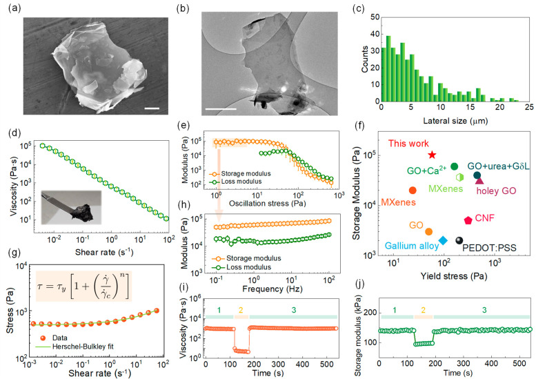
Figure 1.
a,b) SEM and TEM images of the two-dimensional PG platelets used in this work to formulate the graphene inks (scale bars 900 nm and 1 μm, respectively). c) Histogram reporting the lateral size of PG platelets, as determined from SEM imaging. d) Viscosity curve for the PG inks and (inset) picture of the PG ink after homogenization and e) amplitude sweep tests showing the storage (G′) and loss (G″) moduli as a function of oscillatory stress. f) Comparative yield stress and storage modulus of the PG ink with previous literature based on DIW inks for an energy device (references can be found in Table S2). g) Shear stress curve for the PG ink and Herschel-Bulkley equation used to fit the corresponding curve (inset). h) Frequency sweep test performed in the linear viscoelastic region for the PG inks and j) three interval thixotropy tests (3ITTs) showing the recovery of viscosity (i) and storage modulus (j) after a high-shear step (step 2, highlighted in orange).

