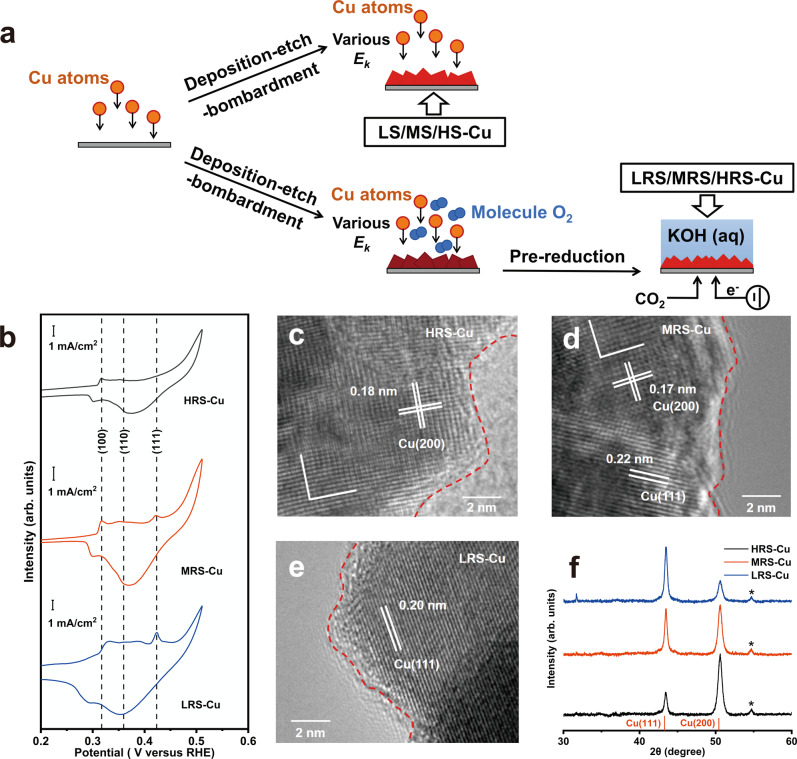
Fig. 1. characterization of various Cu films.
a A schematic illustration of the synthesis process for LS/MS/HS-Cu and LRS/MRS/HRS-Cu. b Voltammograms of resulting electrodes collected immediately after pre-reduction. Typical TEM images of c HRS-Cu, d MRS-Cu, and e LRS-Cu. f Typical XRD patterns of resulting electrodes. As visual aids, the red dash line indicates the surfaces of the resulting electrodes. The precatalysts of HRS/MRS/LRS-Cu were pre-reduced under −0.5 V versus the RHE for 1 h, and the other conditions of prereduction are the same as that of the CO2 reduction. The labeling of Cu(200) is used for easier comparison with XRD, in which only (200), the second-order diffraction of (100) could be detected. The peaks marked with an asterisk in XRD patterns originate from carbon-based GDL substrate.

