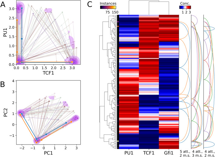
Fig. 4.
Dynamics of a three-node T cell subnetwork. Structure of the modeled network is shown in Fig. 2d. a Scatter-line plot of example tetrastable systems on axes of user-specified molecules’ concentrations, here TCF1 and PU1. Each line represents one system, i.e. one parameter set, that gave rise to four distinct attractors. Each point connected by a line shows the location of a distinct attractor in concentration space. The foreground thick lines represent systems where PU1 concentration never increases as TCF1 concentration increases. Contour shading reflects kernel density estimate for locations of all tetrastable systems’ attractors such that 70% of the total density is inside the pink shaded regions. b The same systems plotted on principal component axes. Over half of the attractors fall within one of three small clusters delineated by the second level of shading (52.5%). c Biclustered heatmap of attractors produced under various parameter sets tested. Attractors belonging to the same parameterization of the network are connected by a series of arcs on the right. System arcs are grouped by the number of attractors (att.) and monotonically correlated species (m.s.). Monotonic correlations of all species represent ordered attractors that may govern stepwise lineage commitment such as that of T cells [36]. Attractors within a given distance in concentration (conc.) space, here 0.2, are “folded” together and represented by one heatmap row, with brighter color along the thin left strip indicating more attractors represented by the row. The set of systems and/or system connections can be “downsampled” to reduce clutter. Here, only 10% of four-attractor or five-attractor systems discovered by the testing of one million parameter sets are shown and at most 5 systems of three selected types are connected by arcs. Gene clustering, arcs, folding, and downsampling are optional

