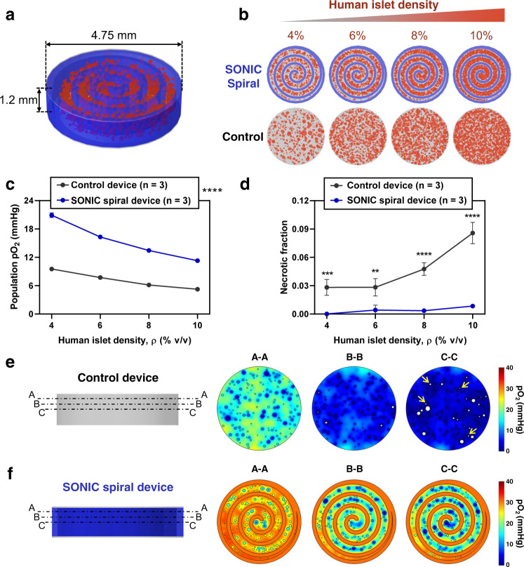
Fig. 7. Computational exploration of a SONIC spiral device for delivering a clinically relevant islet dose.
a Annotated schematic of the central section of a hypothetical SONIC spiral device, including the SONIC scaffold (blue) arranged in an Archimedean spiral (with the distance between turns fixed at 500 μm) and hydrogel-encapsulated human islets (red). A thickness of 1.2 mm ensures a maximum distance of insulin diffusion of 600 μm; a diameter of 4.75 mm was used for simulations, representing the central section of a device scaled radially to achieve a sufficient encapsulated islet payload. b Schematics showing the SONIC spiral device and scaffold-free control device encapsulating 4%, 6%, 8%, and 10% human islets (volume of islets per volume of device), as tested in the simulations. c, d Simulation predictions of the mean islet population pO2 (c) and fraction of necrosis (d) of human islets encapsulated at variable densities in the SONIC spiral device (n = 3) and the scaffold-free control device (n = 3); mean ± SD; c: ****p < 0.0001 (control device versus SONIC spiral device at all islet densities); d: ***p = 0.0004 (control device versus SONIC spiral device at 4% islet density), **p = 0.0018 (control device versus SONIC spiral device at 6%), ****p < 0.0001 (control device versus SONIC spiral device at 8% and 10% islet densities). Statistical tests in c and d were analyzed via a two-way ANOVA followed by Sidak’s post hoc p-value adjustment for multiple comparisons. e, f Surface plots of pO2 gradients (right) at selected cross-sections (left; labelled A-A, B-B, and C-C) in the control device (e) and the SONIC spiral device (f) at 8% human islet loading density showing significantly higher pO2 and negligible necrosis in the SONIC spiral device compared to the control device (white regions in the islets represent necrosis, and yellow arrows in C-C section indicate necrosis even in some small islets).

