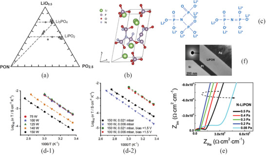
Figure 5.

a) LiO0.5‐PON‐PO2.5 ternary phase diagram with a dashed line showing changes of N concentration from bare Li3PO4. Reproduced with permission.[ 36 ] Copyright 1969, Elsevier. b) The unit cell of LiPON. Reproduced with permission.[ 37 ] Copyright 2016, Elsevier. c) Crosslinked LiPON through N triply bond. d) Arrhenius plots of the ionic conductivities at different deposition parameters: d‐1) influence of power density of rf‐sputtering, and d‐2) effect of bias potential. Reproduced with permission.[ 48 ] Copyright 2018, Elsevier. e) Impedances of LiPON thin films at a different partial pressure of N2 gas. Reproduced with permission.[ 49 ] Copyright 2018, Elsevier. f) The cross section of LiPON on Pt sublayer deposited using IBS technique showing extremely smooth surface. Reproduced with permission.[ 52 ] Copyright 2015, Elsevier.
