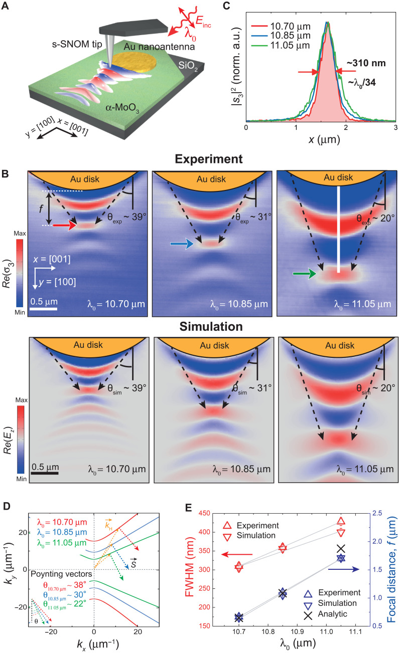
Fig. 2. Planar focusing of in-plane hyperbolic PhPs with Au disk nanoantennas.
(A) Schematics of the s-SNOM experiment to image the propagation and focusing of in-plane hyperbolic PhPs excited by a Au disk nanoantenna on an α-MoO3 slab. The sample is illuminated with p-polarized IR light of wavelength λ0. (B) Experimental [Re(σ3); top row] and simulated [Re(Ez); bottom row] near-field images of PhPs launched by a Au disk nanoantenna fabricated on top of a 165-nm-thick α-MoO3 crystal at λ0 = 10.70 μm (left), λ0 = 10.85 μm (middle), and λ0 = 11.05 μm (right). The interference of PhPs with wave vectors launched from the edges of the antenna yields a focal spot with varying size and f as a function of λ0. The dashed arrows mark the angle θ. (C) Experimental near-field amplitude |s3|2 profiles along the x axis at positions marked with an arrow in (B) for λ0 = 10.70 μm (red), λ0 = 10.85 μm (blue), and λ0 = 11.05 μm (green). A deep subwavelength spot size of λ0/34 (~310 nm) is measured for λ0 = 10.70 μm. (D) Analytical IFCs for a 165-nm-thick α-MoO3 crystal at λ0 = 10.70 μm (red), λ0 = 10.85 μm (blue), and λ0 = 11.05 μm (green). The Poynting vector of PhPs with wave vectors forms wavelength-dependent angles θ with respect to the y axis. (E) Dependence of the experimental, simulated, and analytically calculated values of the spot size (FWHM) and f with λ0 (gray lines serve as a guide for the eye).

