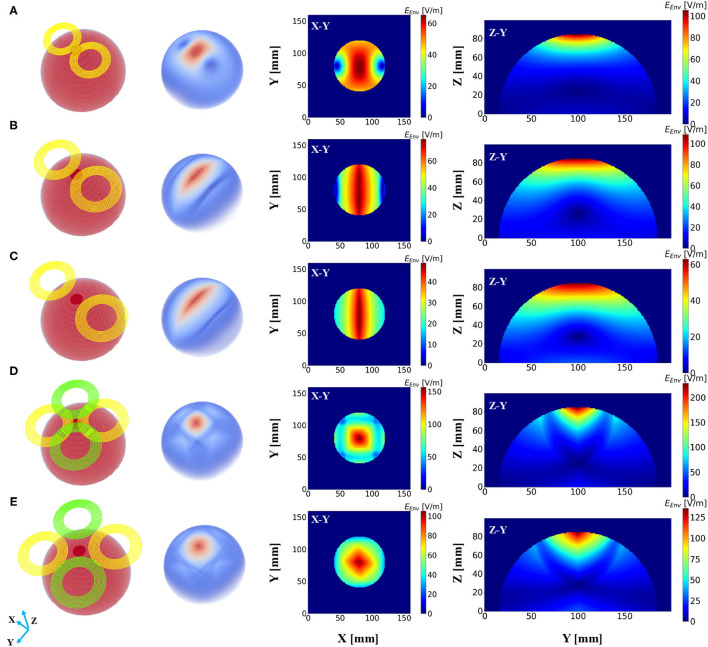
Figure 3.
Electric field distribution in the hemispherical model induced by distinct stimulation protocols. The first column shows the geometry of the stimulation coils, and the second column shows the overall dispersal of the inferential field. Cross-sections of the model from different direction axes are displayed in the last two columns. The current intensity in all the coils was determined to be 1 kA. (A) Magstim 70 mm figure-8 coil (P/N 9925, 3190). (B) Two-coil temporal interference magnetic stimulation with an edge distance of 10 mm. (C) Two-coil temporal interference magnetic stimulation with an edge distance of 40 mm. (D) Four-coil temporal interference magnetic stimulation with an edge distance of 10 mm. (E) Four-coil temporal interference magnetic stimulation with an edge distance of 40 mm.

