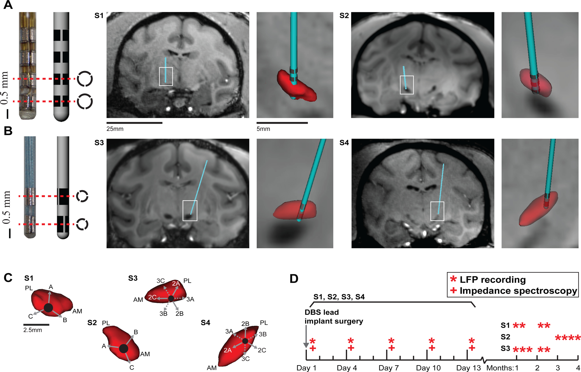
Figure 1.

Directional DBS lead implants and experimental timeline. (A) DBS lead with 12 segmented electrodes in a 4 × 3 configuration implanted in the STN of subjects 1 and 2. MRI-T1 images are shown for each subject with segmented reconstructions of the DBS lead (cyan) and STN (red) overlaid on the images. (B) DBS lead with six segmented electrodes in a 2 × 3 configuration was implanted in the STN of subjects 3 and 4. (C) Radial orientation of electrodes relative to the STN (red) for each subject. View is in a plane perpendicular to the oblique DBS lead trajectory. AM-anteromedial; PL-posterolateral. (D) Experimental timeline marks the day of implant and subsequent LFP recordings and impedance spectroscopy measurements.
