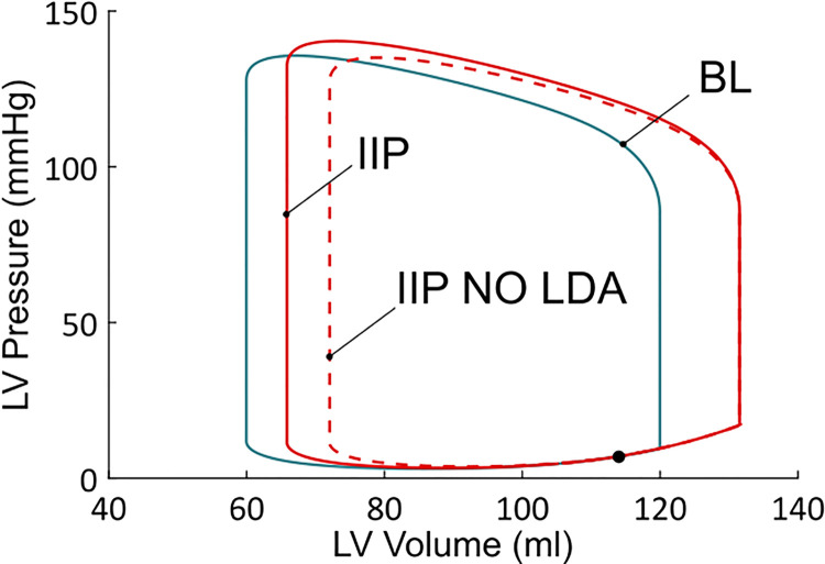
Fig 7. Left ventricular PV loops from the BL, IIP and IIP NO LDA simulations.
IIP starts during ventricular filling (black dot). PV loop for the baseline case (blue) corresponds to a stabilized behavior (each heartbeat leads to that same PV loop). On the other hand, the two PV loops for the IIP protocols (red dashed or solid lines) correspond to a transient response to a preload change. The behavior is not stabilized yet, as this would take several more heartbeats to return to the baseline state. Those PV loops are thus not closed, but this it cannot be seen in the picture.

