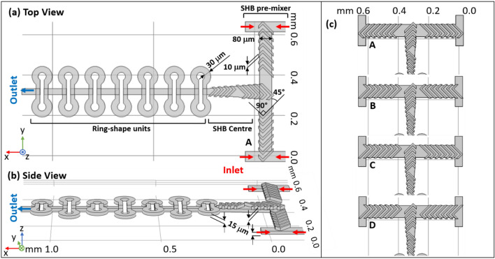
Figure 1.
The structure details of the complete mixing compartment studied in this paper in top (a) and side views (b). The mixer is composed of three zones: SHB pre-mixer, SHB center channel and ring-shape units. The mixer region is built out of two separate layers: the top one contains the SHB ridges and the bottom one the double-T pre-mixer channel. Several ring-shaped units are also combined with the main channel on the bottom layer during fabrication. (c) The four different arrangements of the SHB including the one shown in (a,b), for a total of four SHB designs for the double T structure, marked A, B, C and D. The 3D sketches shown on this figure were made with the SOLIDWORKS 2020 software (http://www.solidworks.com).

