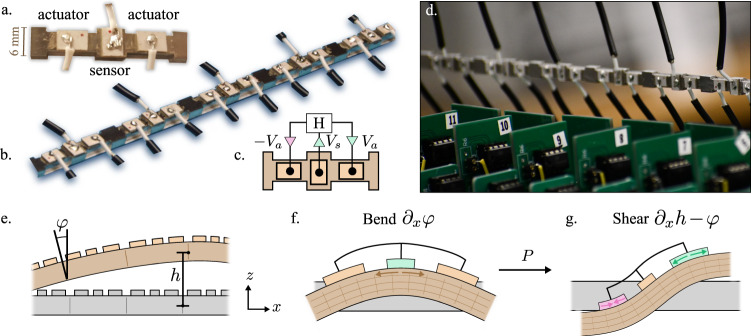
Fig. 1. Design and mechanics of an odd micropolar metabeam.
a A single unit cell featuring three piezoelectric patches mounted on a beam: one that acts as a sensor, and two that act as actuators. b A segment of the full metabeam. c Each unit cell has an electronic loop. The voltage Vs induced by the central piezoelectric is fed into a transfer function H(ω) = Va(ω)/Vs(ω) that sends opposing voltages Va and −Va to the piezoelectric actuators. d A photograph of the metabeam (horizontal) with the electronic circuits in the foreground. We note that the mechanical forces from the attached wires are negligible. The wires act only as sources of energy and computation, but not of linear or angular momentum. e The motion of the metabeam can be described by two independent fields, φ and h, which parameterize the angular and vertical displacements of the metabeam. Notice that under a reflection about the z-axis, we have φ → −φ and h → h. f When the beam bends, the center piezoelectric is stretched. g The antisymmetric electronic actuation then gives rise to a shearing stress proportional to the modulus P.

