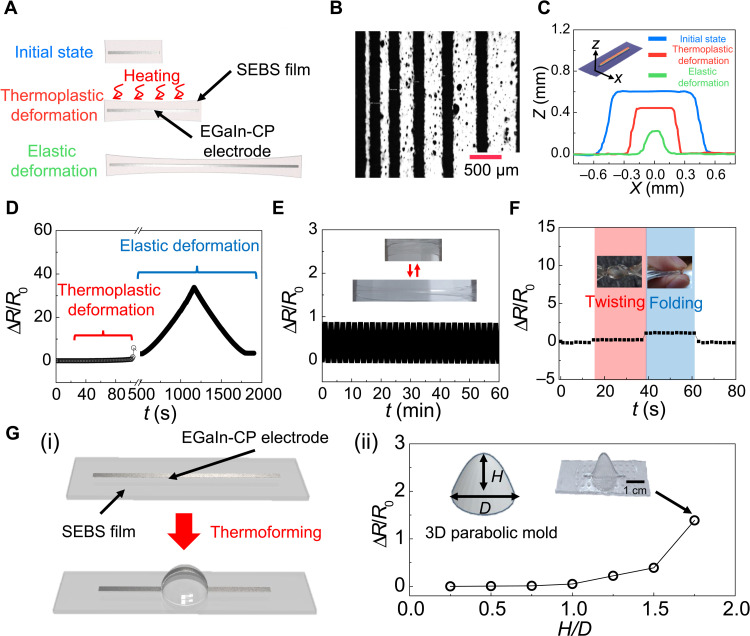
Fig. 4. Electrical characteristics of 3DE based on the PGT3DE.
(A) Schematic illustration of the 3DE with a line pattern of EGaIn-CP electrode during thermoforming process (thermoplastic deformation) and during stretching in the 3DE operation (elastic deformation). (B) Microscope image of line-patterned EGaIn-CP electrodes. (C) Dimension change of EGaIn-CP electrode during thermoforming and stretching in the 3DE operation. (D) Resistance change of the 3DE during thermoforming and stretching in the 3DE operation. (E) Repeatability test of the 3DE with 1000 repeated cyclic loadings of 100% tensile strain. (F) Resistance change of the 3DE during twisting and folding. (G) Resistance change of parabola-shaped 3DE. (i) Schematic illustration of fabrication process. (ii) Resistance change of the parabola-shaped 3DEs after thermoforming using different H/D values of parabolic molds. Photo credit: Jungrak Choi, KAIST.

