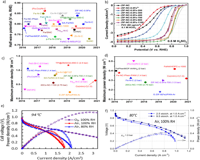
Fig. 6. ORR performances of M–N–C catalysts in RRDE and PEMFCs.
a Half-wave potential of various M–N–C catalysts tested in acidic electrolytes: FePhenMOF–ArNH384, CNT/PC93, Fe–NC–Phen–PANI15, Fe/SNC14, ISAS–Co/HNCS13, FeNC12, Fe2–Z8–C11, Fe–N–C10, (Fe,Co)/N–C97, p-Fe–N–CNFs9, FeSA–N–C92, Co–N–C8, SA-Fe/NG7, SA-Fe–HPC6, Co–N–C@F127105, FeNC–S–MSUFC295, Zn–N–C106, Cr/N/C107, Fe-PANI/BP20005, TPI@Z8(SiO2)–650–C4, ZIF–NC–0.5Fe–70098, Fe–N–C3, and SnNC80. b Steady-state ORR polarization curves showing the effect of activation temperature on the activity of ZIF–NC–0.5Fe98. c and d Maximum power density for PEMFCs using M–N–C as cathode catalysts under H2–O2 (c) and H2–air (d) conditions at 80 °C and 100% RH: c CNT/PC93, Fe–NC–Phen–PANI15, (Fe,Co)/N–C97, Fe2–Z8–C11, 20Co–NC-11008, SA–Fe/NG7, Co–N–C@F127105, E-ZIF–8(Fe)/PAN–Ar128, ZIF–NC–0.5Fe–-70098, TPI@Z8SiO2-650-C4, Co(mIm)–NC(1.0)108, and FeSA–N–C;79 d FePhenMOF–ArNH384, Fe–NC–Phen–PANI15, Fe–N–C129, (Fe,Co)/N–C97, 20Co–NC-11008, E-ZIF–8(Fe)/PAN–Ar4, ZIF-NC–0.5Fe-70098, Co(mIm)–NC(1.0)108, and FeN4/HOPC-c-100099. Pressures are 1.0 bar unless specified otherwise. e Polarization and power density curves obtained under air and O2 for MEAs prepared from a chemically doped MOF-derived Fe−N−C catalyst. Conditions: 4.0 mg cm-2 loading, I/C of 0.6, Nafion 211 membrane, cell temperature: 94 °C; flow rate H2/air or O2: 200/1000 sccm, 1.7 atm H2/air or O2 partial pressure130. f H2–air fuel cell polarization plots. Cathode: ~4.0 mg cm−2 of (CM + PANI)–Fe–C; air 200 ml min−1 (2.5 stoichiometry at 1.0 A cm−2) and 760 ml min−1 (9.5 stoichiometry at 1.0 A cm−2); 100% relative humidity (RH); and 1.0 bar partial pressure. Anode: 2.0 mgPt cm−2 Pt/C; H2 200 ml min−1; 100% RH; and 1.0 bar partial pressure. Membrane Nafion 211, cell 80 °C, electrode area 5 cm2 12. Panels a and b adapted from ref. 2. Panel e reprinted with permission from ref. 130. Copyright 2019 American Chemical Society.

