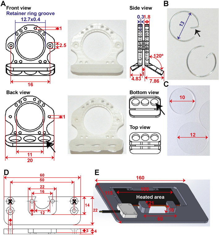
Figure 2.
Design of the window chamber and adaptations to the microscope setup. Shown are the dimension in mm. (A) Shown here are the window frame, the window view area, sutures holes, and holes for the screws (in red). In blue are the dimensions for placement of the retainer rings. The groove is 0.4 mm thick and 0.3 mm deep inside both window frames. The bent hook of the front window is shorter compared to the back frame (see side view) for access of the objective lenses. The three big holes in the back frame (black arrow) are made for air circulation and simultaneous reducing the weight. (B) Retainer rings are made of flexible stainless 0.5 mm thick steel with a diameter of 13 mm. The hook (black arrowhead) serves for easy grip. Retainer rings without hooks can also be used when these interfere for instance with an objective lens. (C) A filler glass of 10 × 0.55 mm is used in the back to keep the skin close to the front glass. Both front and back window view area are closed with a standard 12 mm cover glass or in case of repeated evaluation with a 12 mm gridded coverslip. (D) Schematic overview of the chamber holder. (E) Schematic overview of the temperature-controlled chamber-to-stage platform.

