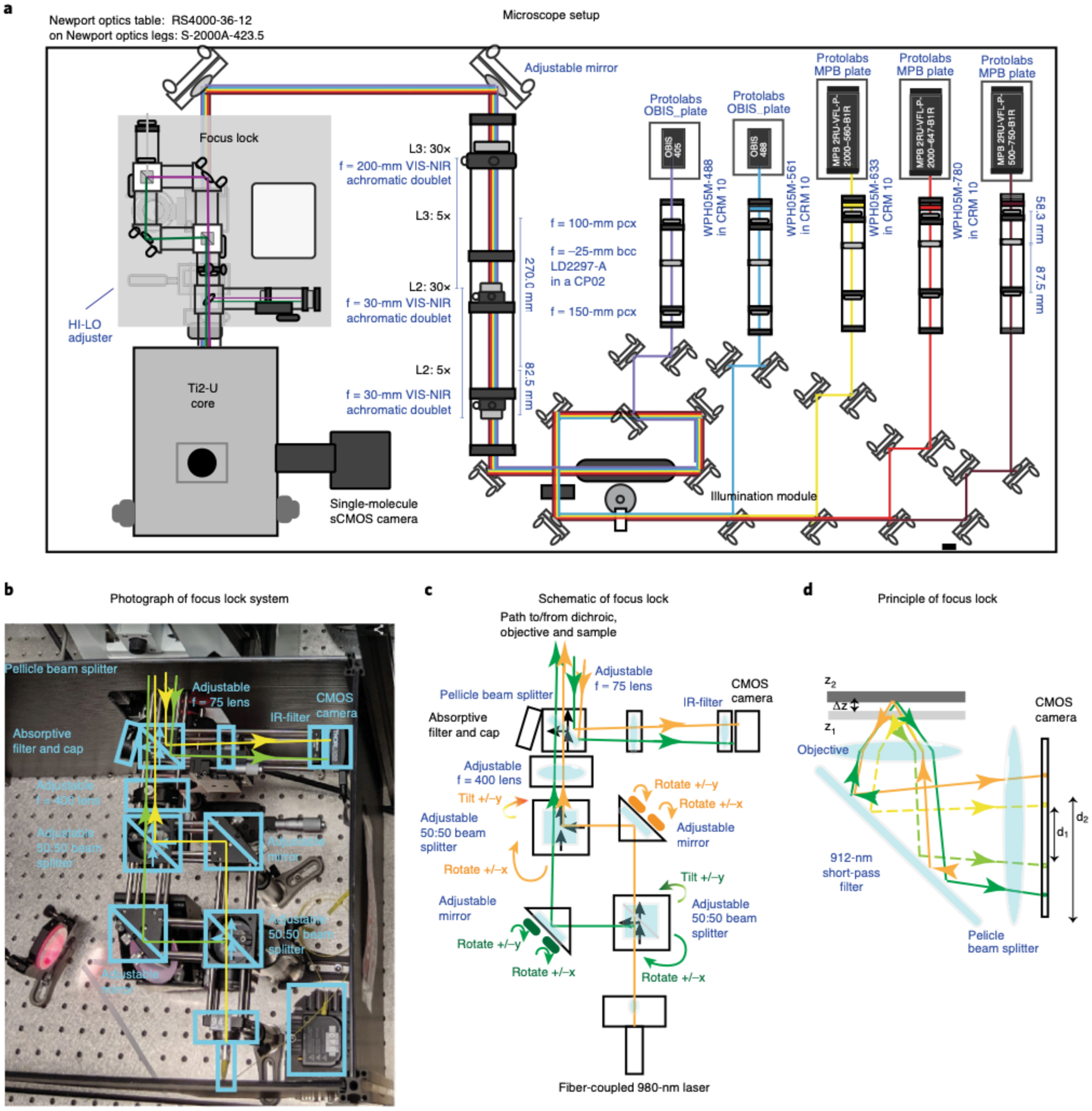
Fig. 5 |. Homebuilt microscope.

a, Schematic layout of the custom-built microscope with components labeled (information about the parts can be found in Supplementary Data 5). The 405-nm, 488-nm, 560-nm, 647-nm, and 750-nm laser paths are illustrated. The laser beams were combined using dichroics and directed based on custom polychroic mirrors placed on top of a high-performance optical table. b, Photograph of the custom Focus Lock system showing the parts used to properly align the beam path. The names of the key optical components are labeled. The beam path for the two 980-nm beams are illustrated in yellow and green. For simplicity, unused branches at the beam splitters are not shown. c, Schematic illustration of the beam path for the Focus Lock. All optical components are indicated. The green and orange paths trace the split 980-nm laser beam. The controls for separately adjusting the two beam paths are indicated in matching colors. d, Schematic illustration of the operating mechanism of the Focus Lock: how a small displacement in z is projected into a large displacement in the separation of the reflected laser beam. Dotted line and solid line show alternate paths for two different focal planes. Closed-loop active feedback is achieved with a precision piezo-z stage to maintain the distance between the two reflected beams.
