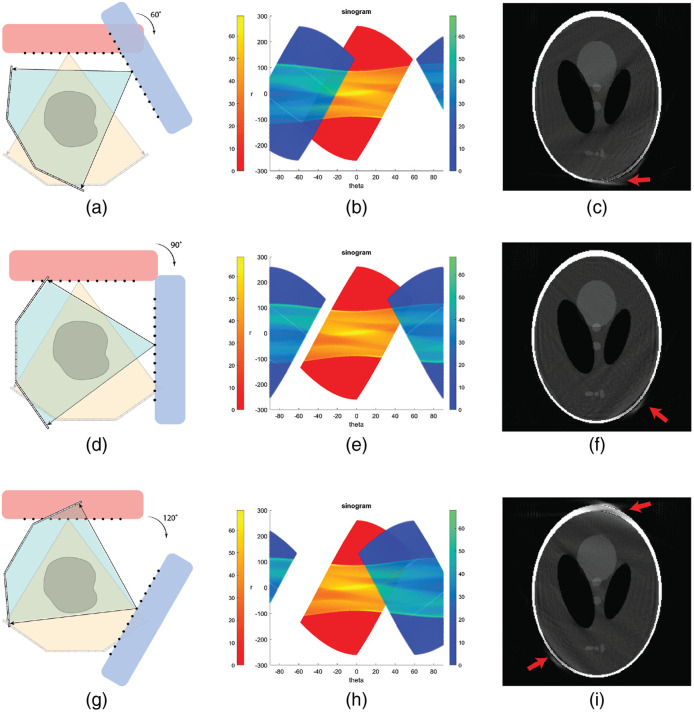
Fig. 10.
Two source–detector pair configurations and reconstruction using HCSL phantom. (a)–(c) Layout, sinogram and reconstructed image for a two source–detector pair configuration with the second pair rotated by 60 deg. (d)–(f) Layout, sinogram and reconstructed image for a two source–detector pair configuration with the second pair rotated by 90 deg. (g)–(i) Layout, sinogram and reconstructed image for a two source–detector pair configuration with the second pair rotated by 120 deg. Display window: [0, 1].

