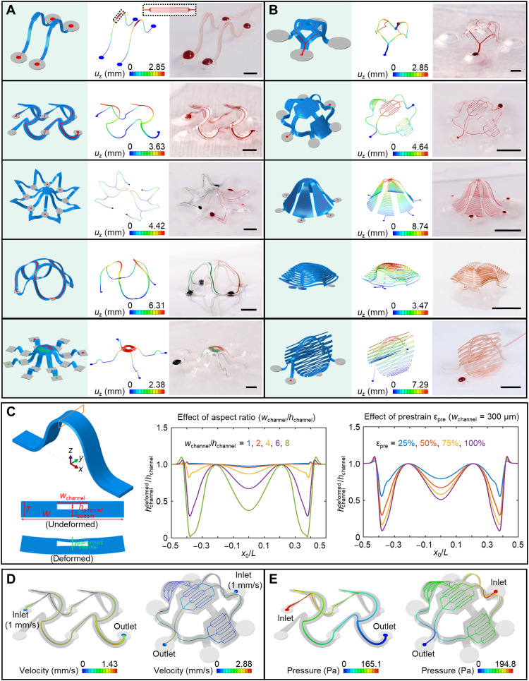
Fig. 2. Assorted 3D microvascular structures formed by mechanically guided assembly.
(A) Ribbon-type 3D structures. The magnified inset on the top highlights seven parallel microchannel branches with widths of 4 μm after 3D assembly. (B) Membrane- and membrane/ribbon-type 3D structures. (C) FEA predictions for the deformation of a microfluidic channel after 3D assembly. Left: Schematic illustration of the 3D shape of a ribbon, highlighting the deformation that can occur in the top cover of the microfluidic channel. Illustration of the deformation of the midspan cross section after assembly. Middle: Effect of the microchannel aspect ratio on the deformation. Right: Effect of the prestrain level on the deformation. x0/L stands for the normalized undeformed coordinate (i.e., undeformed coordinate over length) along the axial direction of the 3D structure. Distribution of fluid velocity (on middle plane) (D) and pressure (E) in the microchannels. Scale bars, 1 mm for the top two structures in (A) and the top structure in (B) and 5 mm for the others. Photo credit: H. Luan, Northwestern University.

