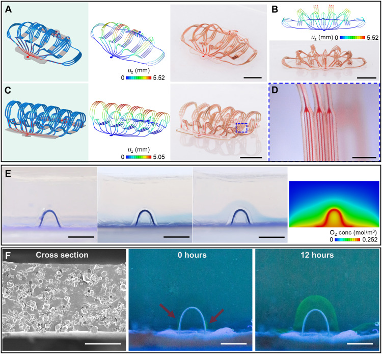
Fig. 4. Characterization of artificial microvascular networks.
(A to D) 3D artificial microvascular system with layout comparable to a biological vascular network composed of arteries, arterioles, capillaries, venules, and veins. The narrowest microfluidic channel branches have widths of 10 μm. (A) 3D microvascular network with filaments fully spread apart. (B) Approximate front view of this 3D network. (C) 3D network with filaments oriented approximately upright. (D) Magnified optical image of the filaments, with microfluidic channels that have widths of 10 μm. (E) Images that show oxygen delivery through a 3D microfluidic channel in a block of oxygen-sensitive hydrogel that changes from colorless to blue in the presence of oxygen. Leftmost: Device in vacuum. Middle left: Device with the microfluidic channel sealed but the elastomer substrate (Dragon Skin 10 SLOW) open to air allows oxygen diffusion. A blue layer forms in the hydrogel near the substrate. Middle right: Device with the channel and the substrate open to air. An arch-shaped blue region forms in the hydrogel in regions along the channel and substrate. Rightmost: Result of an FEA diffusion model showing the oxygen concentration in the block of hydrogel with the channel and the substrate open to air (midsectional view). (F) Experimental demonstration of transport of macromolecular nutrients (e.g., BSA) through a microporous 3D microfluidic channel. Scale bars, 5 mm (A to C, E, and F, middle and right), 1 mm (D), and 50 μm (F, left). Photo credit: H. Luan, Northwestern University.

