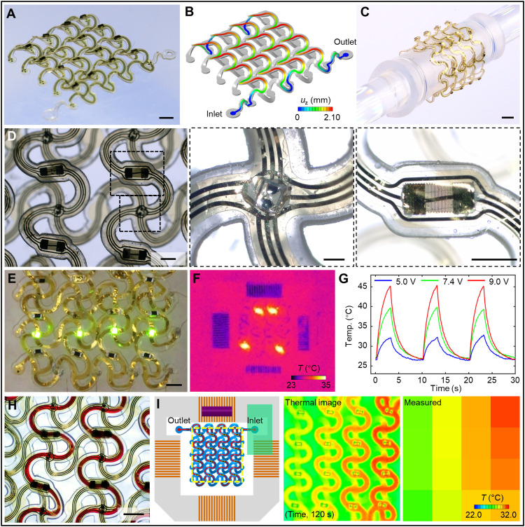
Fig. 5. 3D hybrid microfluidic and electronic systems in the form of extended, interconnected 4-by-4 double-floor helical arrays of 3D microvascular networks with electronic interfaces.
(A) Optical image of a 3D system with integrated electronic components (μ-ILEDs, heaters and thermistors, and electrodes). (B) FEA results for the shape of the 3D microchannel. (C) Image of a soft, stretchable hybrid system wrapped around a glass rod (6 mm in diameter). (D) Top view optical image of the system, with magnified views of a μ-ILED and a microfabricated serpentine trace, respectively. (E) Image of μ-ILEDs during operation. (F) Infrared image of local heating performance. (G) Plot of temperature versus time near a heater element during cyclic operation (10-s period and 3-s duty cycle). (H) Image of the flow of red aqueous dye in the microchannel. (I) Results of temperature mapping during injection of hot water through the 3D microchannel, captured by both an infrared thermal imaging camera (middle) and the integrated 4-by-4 array of thermistors (right). On the left panel, the yellow dashed rectangle shows the mapping region, with locations of 16 thermistors highlighted. Scale bars, 2 mm (A and C), 1 mm (E and H), 500 μm (D, left and right), and 200 μm (D, middle). Photo credit: H. Luan, Northwestern University.

