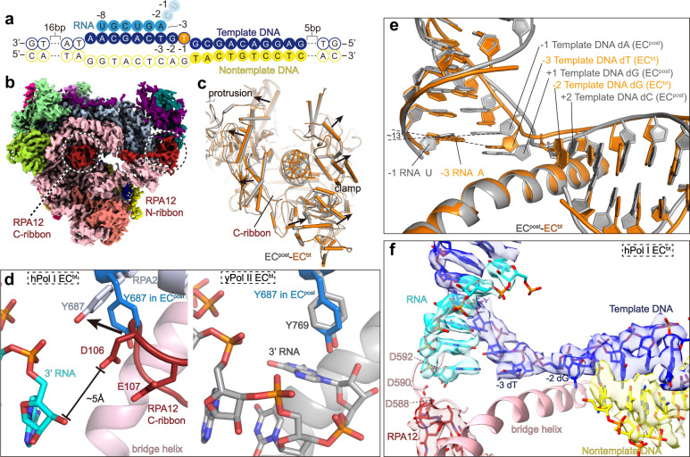
Fig. 4. Structure of Pol I EC in the backtracked state.
a Schematic diagram of the transcription scaffold used in assembly of Pol I ECbt. The dA−1 in template strand was changed to dT−1, generating mismatched base pair of DNA–RNA hybrid. The U−1 and C−2 of the RNA were cleaved in the assembled ECbt. b Cryo-EM map of ECbt shows that the C-ribbon of RPA12 is inserted into the active site. c Structure comparison shows that the cleft of ECbt (orange) is wider than that of ECpost (gray). d Left panel shows the close-up view of the tip of RPA12 C-ribbon in the active site and its interaction with the gating tyrosine and 3′ end RNA. Residue Y687 in ECpost is shown in sticks and colored in marine. Conformational difference in residue Y687 in the two states is indicated with black arrow. Right panel shows the same view of yPol II ECbt without TFIIS (gray; PDB: 3GTJ)42. Residue Y687 in hPol I ECpost is shown (marine) for comparison. e Comparison of the DNA–RNA hybrid in hPol I ECbt (orange) and ECpost (gray). f Cryo-EM map and structural model of catalytic center of the Pol I ECbt. Cryo-EM map is shown in transparent surface.

