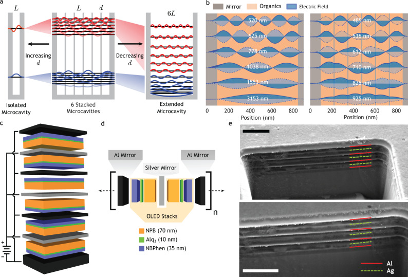
Fig. 1. Stacked microcavity OLEDs.
a Schematic showing the formation of energy bands through the interaction of the isolated single-cavity and extended cavity modes. Increasing the mirror thickness reduces the bandwidth, compressing the states to those of the single-cavity. Reducing the mirror thickness increases the bandwidth, and the states approach the extended cavity modes. b Transfer matrix simulations of the internal electric field profiles at normal incidence of the first photonic band of an ideal extended cavity of length 6L = 720 nm (left) and an ideal six-layer stacked microcavity device with L = 120 nm and d = 10 nm (right). Perturbation of the states by the internal mirrors increases their energy. c Device schematic of a six-layer stacked microcavity device with alternating Al and Ag mirrors of uniform 30 nm thickness. The microcavities are electrically driven in parallel with shared anodes and cathodes. d Schematic of a single unit cell of the photonic crystal consisting of two identical OLED devices with opposite orientation. Mirror thicknesses were varied between 10 and 30 nm. NPB (N,N'-Bis(naphthalen-1-yl)-N,N'-bis(phenyl)-benzidine), Alq3 (Tris-(8-hydroxyquinoline)aluminum, NBPhen (2,9-Bis(naphthalen-2-yl)-4,7-diphenyl-1,10-phenanthroline). e Cross-sectional SEM image of an N = 6 device taken at 45∘ tilt prepared by focused ion beam, using secondary electron (top) and backscatter (bottom) detectors. Scale bars 1 μm.

