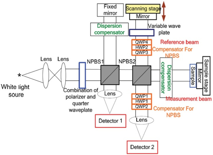
Figure 14.
Schematic illustration of the Mueller OCT system consisted of a halogen lamp, two photo-detectors, a scanning stage, a scanning stage driver, a dispersion compensator, an oscilloscope, and two nonideal beam splitters. Compensation for the polarization distortion was performed using a composite polarizer component comprising a quarter-wave plate, half-wave plate, and second quarter-wave plate. Reprinted with permission from [62].

