Fig. 2.
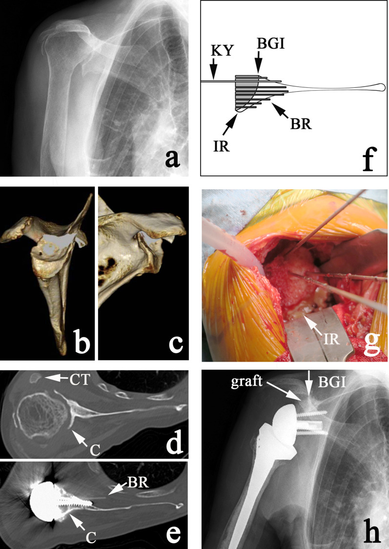
Figs. 2-A through 2-H Multiple bioresorbable pinning (MBP)-assisted structural humeral bone graft. Fig. 2-A Preoperative anteroposterior radiograph. Fig. 2-B Preoperative 3D CT demonstrating massive E2 (superior) glenoid erosion. Fig. 2-C Preoperative 3D CT demonstrating massive B2 (posterior biconcave) glenoid erosion. This deformity is B2, E2, indicating a multiplanar biconcave deformity. Fig. 2-D Preoperative axial CT. The Friedman line is defined on the slice immediately below the coracoid tip (CT). Point C = the posterior ridge of glenoid erosion. Fig. 2-E Postoperative axial CT demonstrating the structural humeral graft aligned to the posterior ridge of the glenoid (C). A bioresorbable pin (BR) was accidentally pushed into the subscapularis muscle by an interfering screw. Fig. 2-F Diagram illustrating grafting of the humeral graft. KY = Kirschner wire, BGI = bone-graft interface, BR = bioresorbable pin, and IR = inferior ridge. Fig. 2-G Intraoperative view of the humeral structural graft aligned to the inferior ridge (IR). Fig. 2-H Postoperative anteroposterior radiograph. The surgeon always tries to align the graft to the bone-graft interface (BGI).

