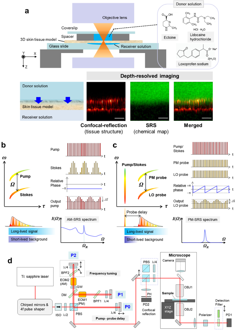
Fig. 1.
Skin penetration test platform based on SRS microscopy. (a) Schematic illustration of the experimental setup. (b)-(c) The process of (b) AM-SRS and (c) PM-SRS, where the diagram of frequency (ω) vs. group delay (τ) and the corresponding temporal pulse shape (left), the RF modulation scheme (upper right), and a typical spectrum (bottom right) are illustrated, respectively. (d) Optical layout of the dual AM-SRS/PM-SRS microscopy system (ISO: optical isolator, BPF: bandpass filter, PBS: polarizing beam splitter, λ/2: half waveplate, λ/4: quarter waveplate, EOM1: PM-electro-optic modulator, EOM2: AM-electro-optic modulator, DM: dichroic mirror, GW: glass window, OBJ: objective lens, PD1 and PD2: photodiodes, PH: pinhole). For confocal-reflection imaging, a PBS and a quarter waveplate were inserted on the beam path in front of the entrance of the microscope. The beam paths of the AM-SRS, PM-SRS and confocal-reflection microscopy modes are illustrated in Fig. S1.

