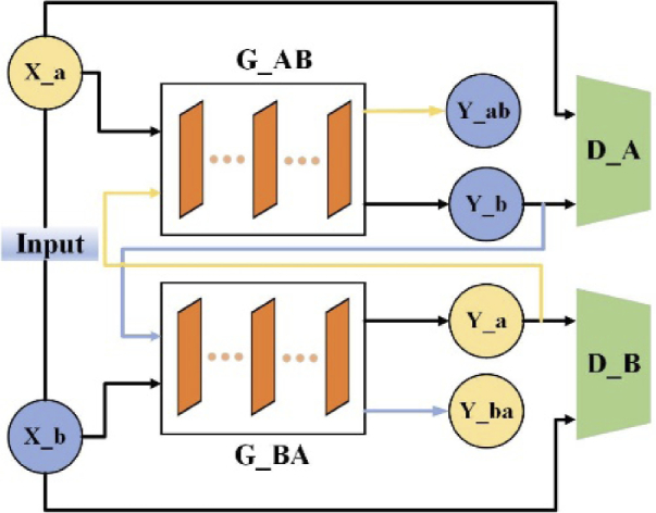
Fig. 1.
Schematic diagram depicting the overall structure of domain transformation network (PA-GAN). PA-GAN uses two generators to achieve the translation between two image domains. The generator translating limited-view photoacoustic tomographic images (domain A) to full-view photoacoustic tomographic images (domain B) is termed as G_AB. The generator achieving the opposite translation is termed as G_BA. The artifact image in domain A, X_a is fed into G_AB to generate the fake artifact-free image (Y_b) in domain B. Y_b as the input of G_BA is cyclically translated into a fake image (Y_ba) in domain A. For the image in domain B, the network executes the same operations. The output of generators passes through the corresponding discriminators to identify the domain of the image.

