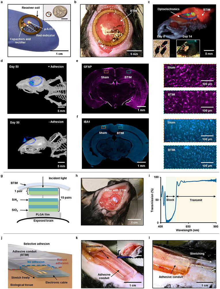
Fig. 4 ∣. Securing optical devices onto the brain and forming adhesives conduits for interconnects.
Wireless optogenetic devices. a, Image of a thin, battery-free wireless device that includes a filamentary probe with a μ-ILED (wavelength: 590 nm) Inset: image of a device placed near a quarter. b, Stable positioning of the receiver coil and interconnects secured by the BTIM. c, Visualization of implanted devices through a combined image that overlays magnetic resonance imaging (MRI) slices with MicroCT reconstructions after two weeks post-surgery. Inset: Deep tissue optogenetic stimulation immediately after surgical implantation (first inset) and at 14 post-surgery days (second inset). d, MicroCT images of the BTIM-encapsulated (first panel) and non-adhesive (second panel) devices on the skull for transcranial optical stimulation day 50 post-surgery. e, f, GFAP (e; colored magenta) and IBA1 (f; colored cyan) staining on the cerebrum directly exposed to the BTIM and the cerebrum sham. (orange inset: sham group; blue inset: BTIM group). Bioresorbable optical filters. g, Cross-sectional illustration of a bioresorbable optical filter secured on an exposed region of the brain by the BTIM. h, Images to illustrate stable positioning of the filter by use of the BTIM with the encapsulation strategy. i, Transmission spectrum of a BTIM-encapsulated, bioresorbable optical filter. Adhesive conduits for interconnects/cables. j, Schematic illustrations of an adhesive ‘tunnel’, or conduit, that anchors the interconnects/cables onto tissues but allows their free motion within. k, l, Images that illustrate stable positioning of an interconnect/cable by an adhesive conduit. The adhesive conduit allows for the interconnect/cable to be bent (inset in k) and stretched during normal use (k). n = 3 biologically independent animals in a-f.

