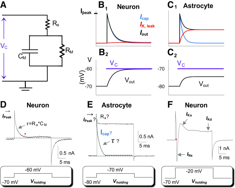
Figure 2.
Characteristics of astrocyte leak K+ conductance. A: Rm and Cm circuit representation of a cell. In voltage-clamp recording, a command voltage (Vc) is applied to the cell through an electrode with an access resistance (Ra) of 5 MΩ in series with membrane resistance (Rm) in the circuit. The Cm is the capacitance of the cell in parallel with Rm. B: in a model neuron, Rm =100 MΩ, a Δ10-mV Vc from resting membrane potential (Vm) −70 mV (B1) induces rapid charge/discharge of the capacitance (Icap, blue) and only small charges through the leak-type K+ channels (IK,leak, red). Iout is the total charge output in response to Vc. B2: Vc-induced output membrane potential (Vout) that is 95% of the Vc. C: in an astrocyte, Rm = 6.4 MΩ, a Δ10-mV Vc from resting Vm −80 mV (C2) induces Icap (blue) and IK,leak (red) that are superimposed (C1). The induced Vout is only 56% of the Vc. D and E: real recordings from a neuron and astrocyte as indicated. In a neuron, at the steady-state baseline marked by *, the neuron is voltage-clamped by the applied Vc. At an Rm=100 MΩ, the Ra,eff is close to the actual Ra, i.e., Ra,eff = RaRm/(Ra + Rm) hence, the Ra can be confidently resolved from Ra = (Vc − Vr)/Ipeak · Cm can be resolved from τ = Cm · Ra and the Rm can be resolved from Rm= Rtotal − Ra· E: applying a Δ10-mV Vc to a low Rm (6.4 MΩ) astrocyte with a low Ra,eff, the actual Ipeak cannot be measured for Ra calculation. An immediate merging of Icap with IK,leak makes it impossible to resolve the τ. F: in a high Rm neuron, the voltage clamping was readily achieved at the beginning of a +Δ50 mV Vc (marked by *), and that was followed by sequential activation of the voltage-gated inward INa, outward IKa, and IKd.

