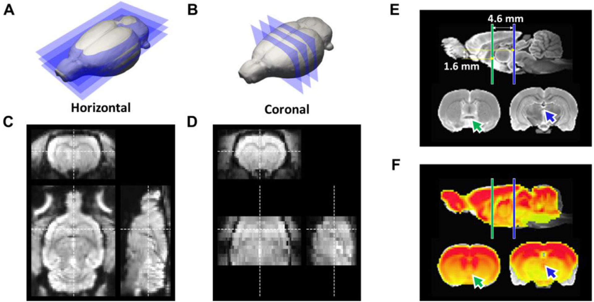
Fig. 3.

Comparison of two EPI protocols and the proposed coordinate system. (A) The proposed horizontal slicing scheme. (B) Conventional coronal slicing scheme. (C) Representative EPI images at 0.4 mm isotropic resolution acquired from horizontal slicing. (D) Representative EPI images with 0.32 × 0.32 × 1 mm anisotropic resolution acquired from coronal slicing. (E) A coordinate system centering at AC, with AC-PC axis alignment identical to the Paxinos and Watson’s (7th edition) rat brain atlas. (F) Co-registered isotropic EPI template on structural MRI template, showing high concordance except the areas prone to susceptibility artifacts, such as amygdala. Green arrow: AC; Blue arrow: PC.
