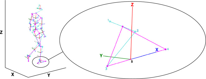
Figure 2.
Local foot coordinate system. Based on digitized anatomical landmarks a model of this example participant was constructed. The full model has been depicted on the left. Magnified is the local coordinate system (X, Y, Z) of the right foot with its anatomical landmarks (light blue circles). The local coordinate system was constructed based on the medial (1) and lateral (2) malleoli, the calcaneus (3) and the second toe tip (4). The origin of the constructed coordinate system lies at the estimated foot’s CoM position (5). The red, dark blue and green lines represent respectively the local vertical (Z), forward (X) and mediolateral axes (Y). We defined our mediolateral CoP shift along the anatomical Y-axis in green. Note that in this figure this mediolateral axis points positively to medial, yet in our analysis we flipped the sign to define a lateral shift as positive and a medial shift as negative. This figure was created using Matlab 2021a (https://www.mathworks.com/products/matlab.html) and Adobe Illustrator CC 2018 (https://www.adobe.com/nl/products/illustrator.html).

