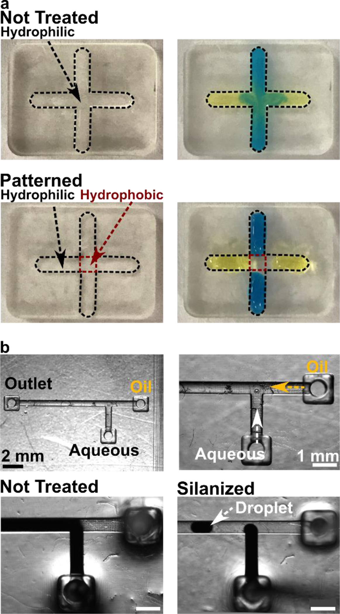
Figure 4:

Application of the optimized silanization procedure for surface patterning and droplet generation. (a) Selective surface patterning of an open channel. Parts printed in BV-007A were patterned so that the center of the cross was hydrophobic. In a non-silanized piece (top), the blue and yellow food dyes mixed in the center; in the piece patterned by local silanization (bottom), the droplets remained distinct from each other. The width of the channels in these photos was 2 mm. (b) Fluorination of 3D printed fluidic channels in a T-junction droplet generator. (Top row) Photos of empty 3D printed chip at low and high magnification, with inlets and outlet marked. (Bottom row) Images of two-phase fluid flow with and without silanization of the interior channels. The dark liquid is the aqueous solution; the fluorinated oil is colorless. Droplets formed only in the silanized system. Scale bar 1 mm.
