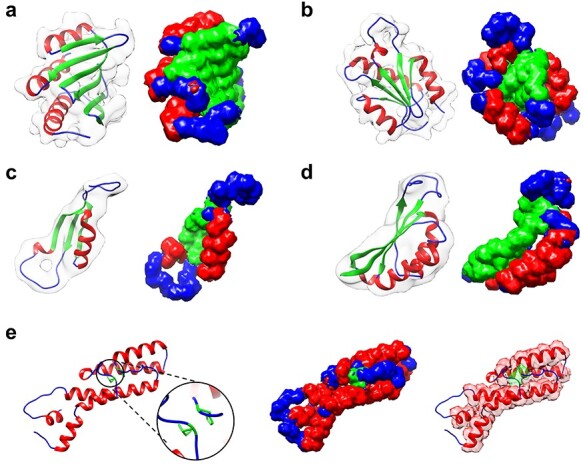
Figure 3 .

Examples of the secondary structure assignment by EMNUSS for the simulated maps at resolutions of 6.0 and 10.0 Å, where helices, strands and coils are colored in red, green and blue, respectively. The raw EM density map in transparent gray is overlapped with deposited PDB structure on the left side of each subfigure and the annotated map predicted by EMNUSS is on the right. (A) 6 Å simulated map for SCOPe entry d1kafa_. (B) 6 Å simulated map for SCOPe entry d1atia1. (C) 10 Å simulated map for SCOPe entry d1b33n_. (D) 10 Å simulated map for SCOPe entry d2cz4a1. (E) SCOPe entry d1a26a1, where the  -bridge structure (in black circle) is successfully detected by EMNUSS for 6 Å (middle) and 10 Å (right) simulated maps.
