
Figure1.
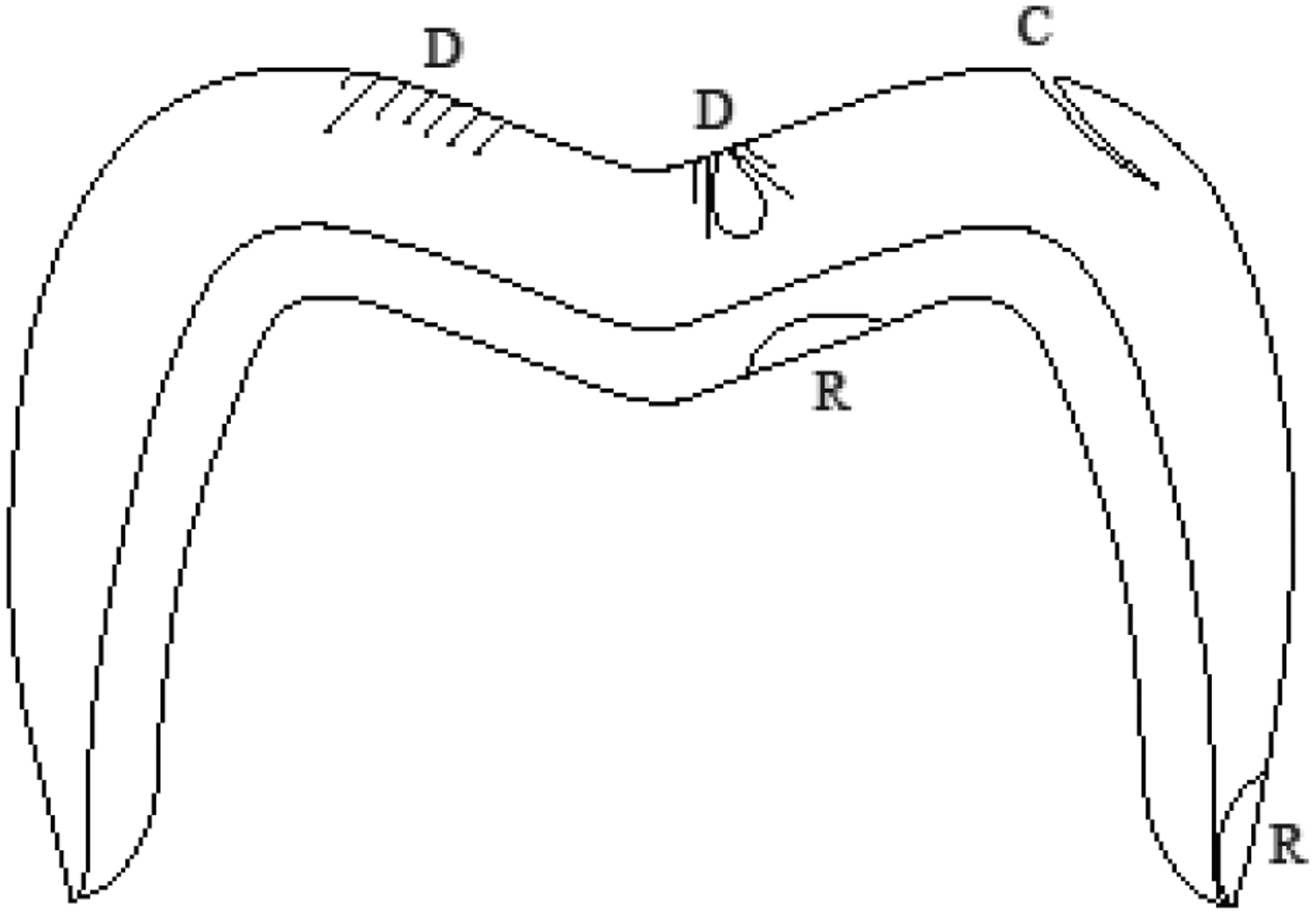
Schematic diagram depicting common fracture modes in bilayer crowns: D shows contact damage, that may propagate causing delamination or chipping, R depicts radial cracks, which lead to bulk fracture or marginal fracture, and C shows edge chipping, originated in the cusp area.