
Table 3.
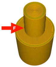
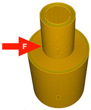
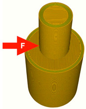
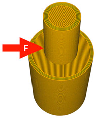
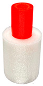
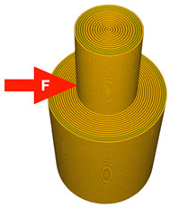
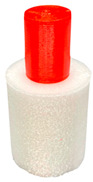
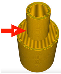
3D model of the printed parts with force point variants, pattern and material configurations, and the number of printed samples.
| A 3D Model with A Visible Pattern |
Pattern Configuration |
Material Configuration/N° | |
|---|---|---|---|
| Bottom: PLA Top: TPU |
Bottom: TPU Top: PLA |
||
|
Bottom part: Lines Top part: Concentric |
 N°−1 |
 N°−1A |
|
Bottom part: Concentric Top part: Lines |
 N°−2 |
 N°−2A |
|
Bottom part: Lines (Line direction: 0°) Top part: Lines (Line direction: 90°) |
Failure N°−3 |
 N°−3A |
|
Bottom part: Lines (Line direction: 0°) Top part: Lines (Line direction: 45°) |
 N°−4 |
 N°−4A |
|
Bottom part: Concentric Top part: Concentric |
 N°−5 |
 N°−5A |
|
Bottom part: Lines 0° Top part: Lines 0° |
 N°−6 |
 N°−6A |