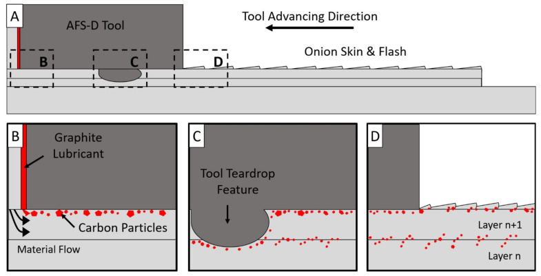
Figure 11.
(A). Overview schematic of the cross section of the AFS-D tool, feedstock, and two layers. (B) Schematic of the material flow close to the tool exit hole. Carbon highlighted in red. (C) Schematic of the area near a tool teardrop feature. Carbon follows the path of the tool features rather than dissolving into the layers. (D) Carbon on the active layer becoming entrapped by the flash from excess material in the onion skin.

