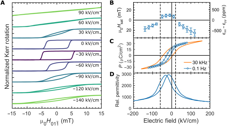
Fig. 3. ME, FE, and piezoelectric properties of PMN-PT membrane heterostructures.
(A) MOKE magnetic hysteresis loops (normalized) at a series of electric fields from −140 kV/cm (−7 V) to 90 kV/cm (4.5 V). Dark colors are closer to the FE imprint, and lighter colors are further from the imprint. (B) Saturation magnetic field (Hsat; left axis) and calculated anisotropic strain (εxx − εyy; right axis) versus biasing electric field extracted from HA MOKE hysteresis loops similar to those shown at high-bias electric field in (A). Error bars represent the SD of measurements of seven different devices on the same membrane. Negative differential strain points (εxx − εyy < 0) were extracted from HA MOKE loops with magnetic field along and positive points (εxx − εyy > 0) from loops where magnetic field was along [100]. (C) Polarization (P) vs electric field hysteresis loop measurements using the 160-μm-diameter Ni/SRO top electrode. The orange loop was measured with a 30-kHz sinusoidal voltage pulse. The blue curve, labeled as 0.1 Hz, was acquired using a quasi-DC measurement procedure (see Methods). (D) Relative permittivity versus biasing electric field. Bias electric field was swept at 0.5 Hz, and permittivity was measured with a small AC electric field of 3.5 kV/cm RMS at 4 kHz. For (B) to (D), guidelines are added to separate the behavior into a low-field region (near FE imprint) and high-field regions.

