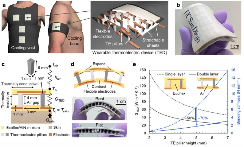
Fig. 12.
Design and fabrication process of flexible TE cooler; (a) Schematic illustration of cooling garment with flexible TE coolers (left) and internal structure of TE (right); (b) Photograph of flexible TE cooler; (c) Schematic illustration of TE design, where hair is heat transfer coefficient, GTED is thermal conductance, Th and Tc are temperatures at hot and cold sides of TE; (d) Schematic diagram and photographs showing the flexibility of the TED; (e) Finite element simulation of GTED and bending stiffness of flexible TE coolers as a function of pillar height [135]. Copyright 2019 AAAS.

