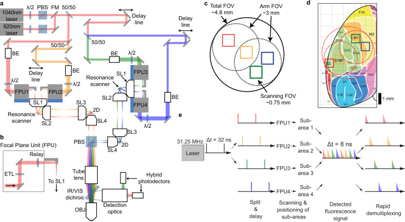
Fig. 1. Large field of view quad area two-photon microscope system.
a Schematic of the Quadroscope system. Laser source is selected by a flip mounted mirror (FM). Laser output is then split into four beam paths (beam 1—red, 2—orange, 3—green, 4—blue) using 50/50 beam splitters (50/50). Each beam is delayed 8 ns relative to the other. Each beam is magnified by a beam expander (BE) entering into the focal plane units (FPUs). Half-wave plates (λ/2) are used in conjunction with a polarizing beam splitter (PBS) to control power of each beam. Two scan engines each control two of the imaging regions. Each scan engine consists of three commercial scan lenses (SL1-3), a resonance scanner, a 2D scanning mirror, and a custom scan lens (SL4) before being combined using the PBS onto a custom tube lens. The beams enter a custom objective (OBJ) before arriving at the sample. A long-pass dichroic (IR/VIS Dichroic) is used to separate the excitation and emission light. b FPU design. Each FPU is mounted on a motorized XY stage and contains an electrically tunable lens (ETL) and relay lens. c Schematic of scan area positioning. Scanning regions of up to ~0.75 mm2 can be achieved for each of the four sub-areas. Each scan arm has a 3 mm arm field of view (FOV) in which sub-areas can be repositioned using the FPU. The arm FOV can be positioned anywhere within the 4.8 mm total FOV using 2D scanning mirrors. d Scanning areas and FOVs overlaid across an atlas of mouse cortex, adapted from ref. 25 with permission. e Spatiotemporal multiplexing of four beams. A 31.25 MHz laser source is split into four beams and delayed to achieve 8 ns inter-pulse intervals. The detected fluorescence signal is then de-multiplexed and assigned to each imaging area.

