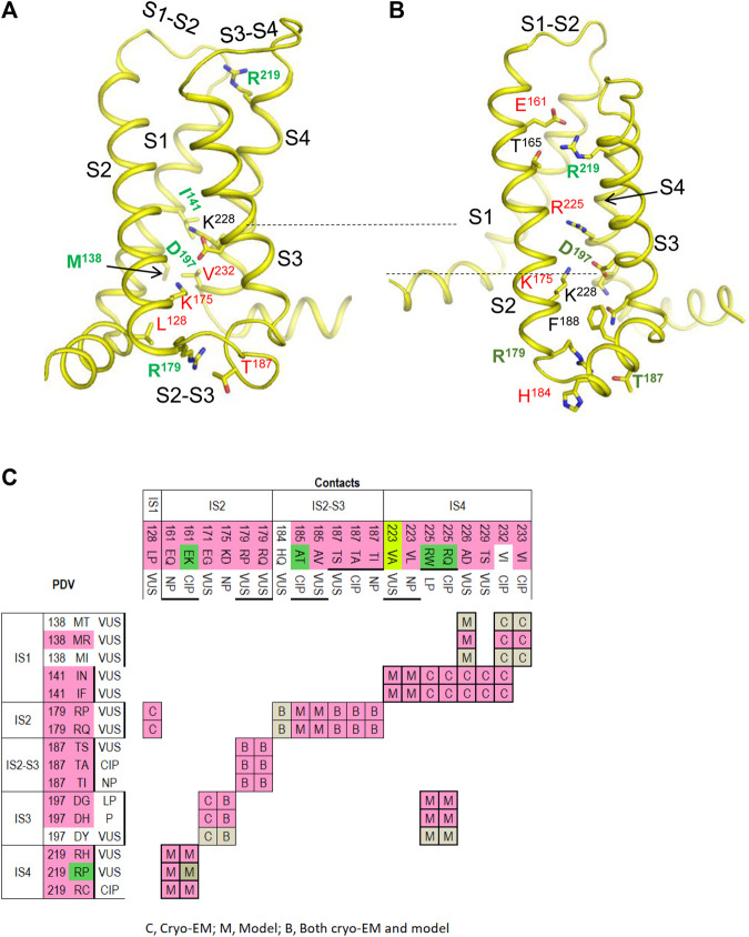
FIGURE 5.
VSD-I in the activated-state structure and resting-state model. (A,B) Intra-membrane views at VSD-I in the activated (A) and resting (B) states. Side chains of some w54 residues and their contacts are indicated with green and red labels, respectively. Dashed lines indicate displacement of K228 upon activation of VSD-I. (C) Matrix of contacts variants. To indicate contacts, which may switch upon activation of VSD-I, each cell is labeled “C”, “M” or “B” depending on whether the contact is found only in the cryo-EM structure, only in the resting-state model, or both in the cryo-EM structure and the model. Overwhelming majority of PDVs and their contact variants are associated with BrS1. See section VSD-I for more details.

