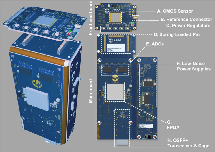
Figure 4: System electronics.
The Argo system’s electronics are housed on two custom PCBs. (Left) PCBs are folded and aligned to fit the metal housing of the Argo system. (Right) A smaller PCB (the front-end board) holds the CMOS sensor (A), reference connector (B), and power regulators (C) for the sensor. This front-end board is connected to a larger main board via three banks of spring-loaded connectors (D). On this main board sit the analog-to-digital converters (ADCs, E), low-noise power supplies (F), the FPGA (G), and the Quad Small Form-factor Pluggable (QSFP+) transceiver and connector (H) over which data are transmitted using an optical fiber (not pictured).

