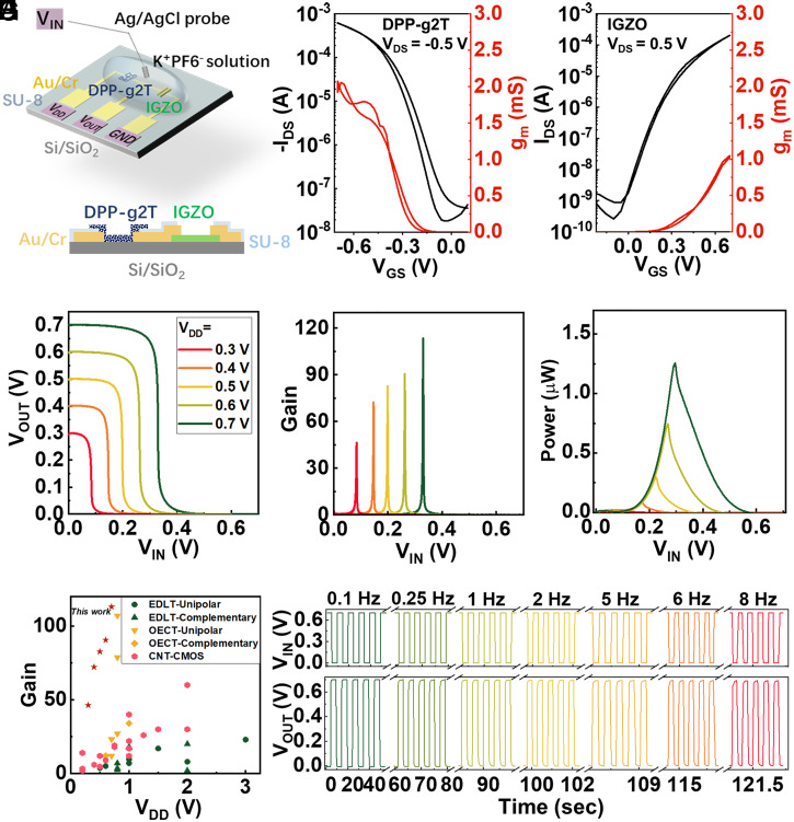
Fig. 1.
Hybrid inverter design and performance. (A) Illustration of the hybrid inverter on rigid Si/SiO2 substrate with top and cross-section views. Representative transfer and transconductance data for (B) p-type OECT and (C) IGZO EDLT. (D) Voltage transfer curves of the HCIN with VDD from 0.3 to 0.7 V, and the corresponding (E) voltage gain and (F) power consumption. (G) Comparison of device voltage gain and VDD of this work to literature EGT-based inverters (EDLT-based unipolar inverters, EDLT-based complementary inverters, OECT-based unipolar inverters, and OECT-based complementary inverters). (H) Dynamic performance of the HCIN with VDD = 0.7 V over a frequency range from 0.1 Hz to 8 Hz.

