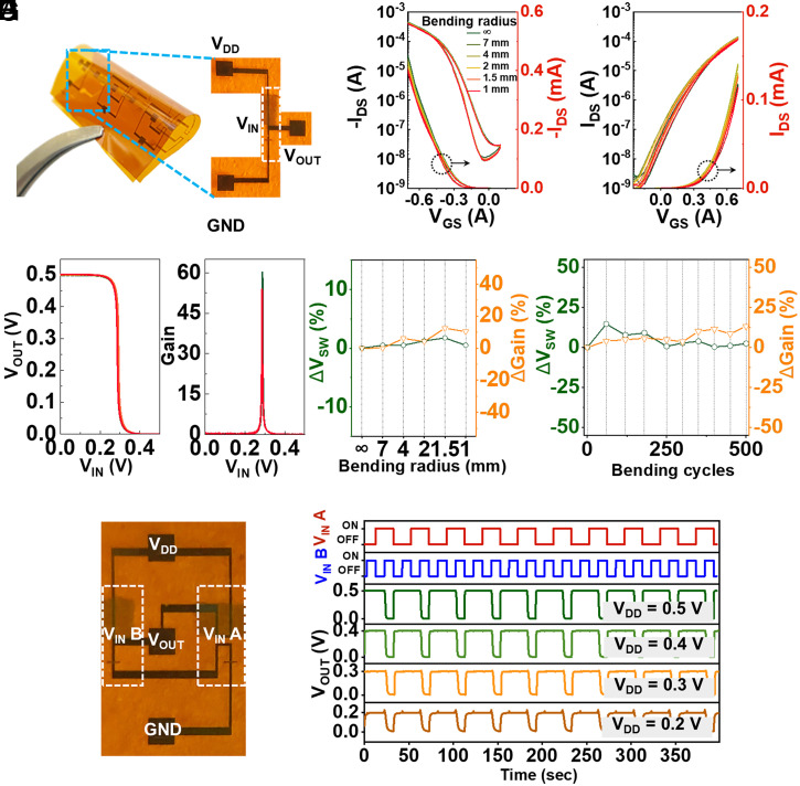
Fig. 4.
Mechanically flexible hybrid complementary circuits. (A) Photo of the flexible hybrid circuits, along with a zoomed-in part of the inverter. Transfer curves of the flexible (B) DPP-g2T OECT and (C) IGZO EDLT when bended at the indicated radius (from 7 mm to 1 mm) along the direction perpendicular to channel length. (D) Corresponding voltage transfer characteristics and voltage gain of the flexible complementary inverter after bended under the indicated radius (from 7 mm to 1 mm). Switch voltage (VSW) and voltage gain variation of flexible hybrid inverter (E) after different bending radius and (F) after multiple bending cycles (bending radius = 4 mm) along the direction perpendicular to channel length. (G) Photo of the NAND gate on PI substrate, along with (H) the dynamic performance of the NAND logic gate with VDD from 0.2 V to 0.5 V.

