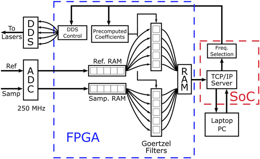
Fig. 2.
Block diagram of data flow through the programmable logic (PL) of the field programmable gate array (FPGA). Data from the reference and sample arms of the HS FD-DOS system were digitized by a high-speed analog to digital converter (ADC) and saved to separate blocks of random access memory (RAM). These data were read sequentially and distributed to 12 Goertzel filters which were used to calculate the Discrete Fourier Transform (DFT) at 6 different frequencies. The results were saved in a separate block of RAM where they could be read by the single board computer (SOC). The SOC was programmed to run a TCP/IP server that was used to communicate with a laptop computer via an Ethernet cable. The laptop was used to set acquisition parameters such as the number of modulation frequencies to be used as well as the number of ADC samples to save for each frequency. This information was passed to the FPGA which was used to tune the Goertzel filters and control the direct digital synthesis (DDS) chips. These improvements increase the acquisition speed by about 3x compared to our prior digital FD-DOS system.

