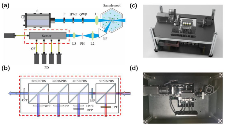
Figure 2.
(a) Schematic of experimental setup. Laser source (S); linear polarizer (P); half-wave plate (HWP); quarter-wave plate (QWP); convex lenses (L1, L2, and L3); equilateral prism (EP); pinhole (PH); optics fiber (OF), photoelectric detector (PD). (b) Analyzer of the polarization and fluorescence. Non-polarizing beam splitter cube (NPBS); long-pass filter (LPF); bandpass filter (BPF); quarter-wave plate (R); polarizer (P); photoelectric detector (PD). (c) Three-dimensional model of the prototype. (d) Top view of the prototype.

