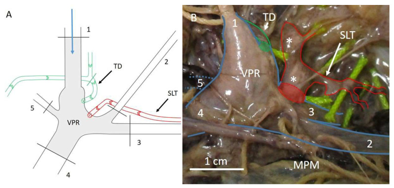
Figure 3.
Schematic representation of the venous reservoir (A) and the venous reservoir in a cadaveric set up (B). The blue arrow in panel (A) represents the cannulation site and the flow direction of the contrast agent upon injection. The numbers represent the venous structures that need to be ligated in order to obtain the venous pressure reservoir. Arrows inside the lymphatic vessels in panel (A) depict the natural direction of lymph flow. Black lines represent ligation sites. The green line shows the ligation site at the thoracic duct, to prevent contrast agent from advancing into the thorax, instead focusing the built up pressure towards the SLT. Note that the external jugular vein (2) is retracted caudally in panel (B), in order to show the SLT that was partially filled with contrast agent as a result of the retrograde injection approach using the venous reservoir. The vertebral vein (5) in panel (B) is depicted as interrupted blue lines, because this structure runs posteriorly from the venous pressure reservoir, obscuring it from view. 1 = internal jugular vein, 2 = external jugular vein, 3 = subclavian vein, 4 = brachiocephalic vein, 5 = vertebral vein, MPM = major pectoral muscle, SLT = subclavian lymphatic trunk, TD = thoracic duct, VPR = venous pressure reservoir, * = lymph node. Green lines = thoracic duct, red lines = subclavian lymphatic trunk, blue lines = venous structures in panel (B). Adapted from Stouthandel et al. [77].

