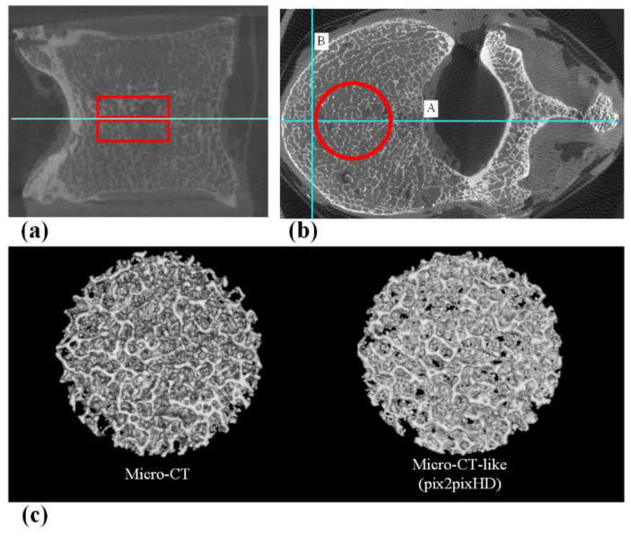
Figure 4.
(a) The sagittal position of the VOI, which includes two areas 5 mm above and below the central slice. (b) The axial position of the VOI. First, the vertebral body central axis line A (Horizontal positioning line) was drawn, and then, line B (Vertical positioning line) was drawn perpendicular to line A at 5 mm inside the intersection of line A and the anterior edge of the vertebral body. Using the intersection of lines A and B as the tangent point, a cylindrical VOI with a diameter of 15 mm was outlined. (c) 3D reconstructed VOI of micro-CT and micro-CT-like images.

